KR QUANTEC extra - KUKA Robotics
KR QUANTEC extra - KUKA Robotics
KR QUANTEC extra - KUKA Robotics

You also want an ePaper? Increase the reach of your titles
YUMPU automatically turns print PDFs into web optimized ePapers that Google loves.
<strong>KR</strong> <strong>QUANTEC</strong> <strong>extra</strong><br />
6.3 Connecting cables and interfaces<br />
Connecting<br />
cables<br />
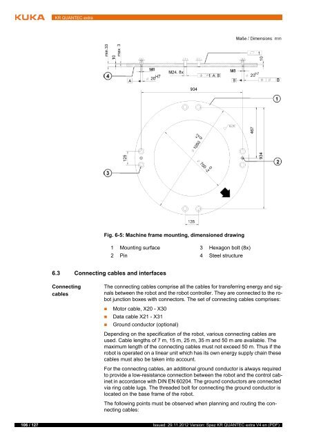
Fig. 6-5: Machine frame mounting, dimensioned drawing<br />
1 Mounting surface 3 Hexagon bolt (8x)<br />
2 Pin 4 Steel structure<br />
The connecting cables comprise all the cables for transferring energy and signals<br />
between the robot and the robot controller. They are connected to the robot<br />
junction boxes with connectors. The set of connecting cables comprises:<br />
Motor cable, X20 - X30<br />
Data cable X21 - X31<br />
Ground conductor (optional)<br />
Depending on the specification of the robot, various connecting cables are<br />
used. Cable lengths of 7 m, 15 m, 25 m, 35 m and 50 m are available. The<br />
maximum length of the connecting cables must not exceed 50 m. Thus if the<br />
robot is operated on a linear unit which has its own energy supply chain these<br />
cables must also be taken into account.<br />
For the connecting cables, an additional ground conductor is always required<br />
to provide a low-resistance connection between the robot and the control cabinet<br />
in accordance with DIN EN 60204. The ground conductors are connected<br />
via ring cable lugs. The threaded bolt for connecting the ground conductor is<br />
located on the base frame of the robot.<br />
The following points must be observed when planning and routing the connecting<br />
cables:<br />
106 / 127 Issued: 29.11.2012 Version: Spez <strong>KR</strong> <strong>QUANTEC</strong> <strong>extra</strong> V4 en (PDF)