KR QUANTEC extra - KUKA Robotics
KR QUANTEC extra - KUKA Robotics
KR QUANTEC extra - KUKA Robotics

Create successful ePaper yourself
Turn your PDF publications into a flip-book with our unique Google optimized e-Paper software.
Interface for<br />
energy supply<br />
systems<br />
Issued: 29.11.2012 Version: Spez <strong>KR</strong> <strong>QUANTEC</strong> <strong>extra</strong> V4 en (PDF)<br />
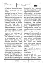
6 Planning<br />
The bending radius for fixed routing must not be less than 150 mm for motor<br />
cables and 60 mm for control cables.<br />
Protect cables against exposure to mechanical stress.<br />
Route the cables without mechanical stress – no tensile forces on the connectors<br />
Cables are only to be installed indoors.<br />
Observe permissible temperature range (fixed installation) of 263 K (-<br />
10 °C) to 343 K (+70 °C).<br />
Route the motor cables and the data cables separately in metal ducts; if<br />
necessary, additional measures must be taken to ensure electromagnetic<br />
compatibility (EMC).<br />
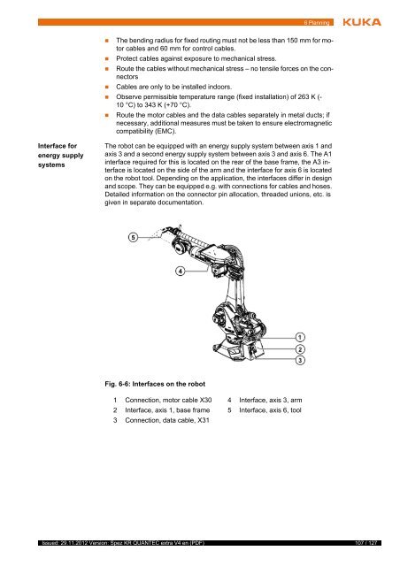
The robot can be equipped with an energy supply system between axis 1 and<br />
axis 3 and a second energy supply system between axis 3 and axis 6. The A1<br />
interface required for this is located on the rear of the base frame, the A3 interface<br />
is located on the side of the arm and the interface for axis 6 is located<br />
on the robot tool. Depending on the application, the interfaces differ in design<br />
and scope. They can be equipped e.g. with connections for cables and hoses.<br />
Detailed information on the connector pin allocation, threaded unions, etc. is<br />
given in separate documentation.<br />
Fig. 6-6: Interfaces on the robot<br />
1 Connection, motor cable X30 4 Interface, axis 3, arm<br />
2 Interface, axis 1, base frame 5 Interface, axis 6, tool<br />
3 Connection, data cable, X31<br />
107 / 127