KR QUANTEC extra - KUKA Robotics
KR QUANTEC extra - KUKA Robotics
KR QUANTEC extra - KUKA Robotics

Create successful ePaper yourself
Turn your PDF publications into a flip-book with our unique Google optimized e-Paper software.
4.5 Transport dimensions<br />
Issued: 29.11.2012 Version: Spez <strong>KR</strong> <strong>QUANTEC</strong> <strong>extra</strong> V4 en (PDF)<br />
4 Technical data<br />
All variants Force/torque/mass<br />
Fv = vertical force Fv max = 24,000 N<br />
Fh = horizontal force Fv max = 16,000 N<br />
Mk = tilting moment Mk max = 49,000 Nm<br />
Mr = torque Mr max = 35,000 Nm<br />
Total mass for load acting on<br />
<strong>KR</strong> 210 R2700 <strong>extra</strong> = 1,328 kg<br />
the mounting base<br />
<strong>KR</strong> 180 R2500 <strong>extra</strong> = 1,289 kg<br />
<strong>KR</strong> 150 R2700 <strong>extra</strong> = 1,268 kg<br />
<strong>KR</strong> 120 R2900 <strong>extra</strong> = 1,254 kg<br />
<strong>KR</strong> 90 R3100 <strong>extra</strong> = 1,232 kg<br />
Robot <strong>KR</strong> 210 R2700 <strong>extra</strong> = 1,068 kg<br />
<strong>KR</strong> 180 R2500 <strong>extra</strong> = 1,059 kg<br />
<strong>KR</strong> 150 R2700 <strong>extra</strong> = 1,068 kg<br />
<strong>KR</strong> 120 R2900 <strong>extra</strong> = 1,084 kg<br />
<strong>KR</strong> 90 R3100 <strong>extra</strong> = 1,092 kg<br />
Total load (suppl. load on arm + rated <strong>KR</strong> 210 R2700 <strong>extra</strong> = 260 kg<br />
payload)<br />
<strong>KR</strong> 180 R2500 <strong>extra</strong> = 230 kg<br />
<strong>KR</strong> 150 R2700 <strong>extra</strong> = 200 kg<br />
<strong>KR</strong> 120 R2900 <strong>extra</strong> = 170 kg<br />
<strong>KR</strong> 90 R3100 <strong>extra</strong> = 140 kg<br />
The mounting base loads specified in the table are the<br />
maximum loads that may occur. They must be referred<br />
to when dimensioning the mounting bases and must be adhered to for safety<br />
reasons.<br />
The supplementary loads on the base frame and rotating column are not taken<br />
into consideration in the calculation of the mounting base load. These supplementary<br />
loads must be taken into consideration for F v .<br />
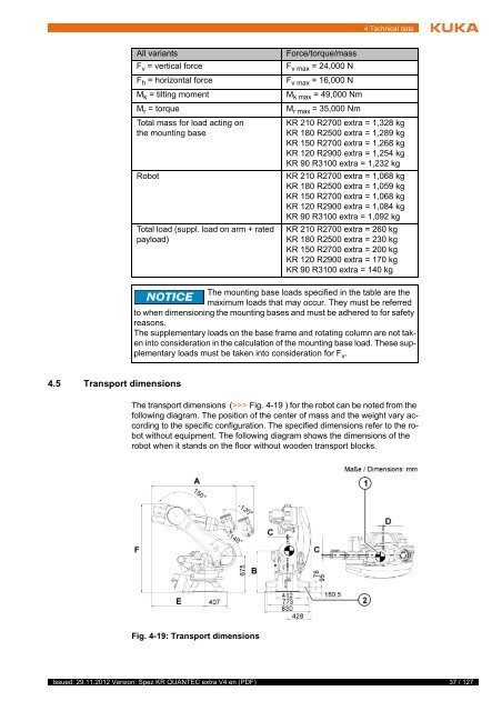
The transport dimensions (>>> Fig. 4-19 ) for the robot can be noted from the<br />
following diagram. The position of the center of mass and the weight vary according<br />
to the specific configuration. The specified dimensions refer to the robot<br />
without equipment. The following diagram shows the dimensions of the<br />
robot when it stands on the floor without wooden transport blocks.<br />
Fig. 4-19: Transport dimensions<br />
37 / 127