Script for Laboratory: Designing embedded ASIPs - CES
Script for Laboratory: Designing embedded ASIPs - CES
Script for Laboratory: Designing embedded ASIPs - CES
You also want an ePaper? Increase the reach of your titles
YUMPU automatically turns print PDFs into web optimized ePapers that Google loves.
When you manually have to fix some falsely generated rules then you have to do it on<br />
this workstation.<br />
• One step of the compiler generation has to be finalized by pressing +C. This<br />
step will print a in<strong>for</strong>mation to let you know when to press +C.<br />
• Except the “makeCoSy” script there also exist a “contCoSy” script (speak: Continue<br />
CoSy). This script is meant <strong>for</strong> continuing the creation of a CoSy compiler, if the initial<br />
creation with “makeCoSy” was aborted with an error message, as shown in Chapter<br />
8.2.2. In such cases you have to manually fix the printed error message (usually on<br />
i80pc06) and afterwards you can continue the compiler creation with the “contCoSy”<br />
script. In fact the contCoSy script will tell you the specific steps that have to be per<strong>for</strong>med<br />
<strong>for</strong> manually continuing the compiler generation. Those steps are single instructions,<br />
that are printed related to your current project name and that can be copied<br />
and pasted to the Linux-shell to per<strong>for</strong>m the needed steps.<br />
8.2.1 Structure of a CoSy rule<br />
To understand the typical problems while creating a CoSy compiler it is important to understand<br />
how the backend is created <strong>for</strong> the CoSy compiler generator. Every assembly instruction<br />
that shall be used in the backend is described by a rule. This rule explains the prerequisites<br />
and the effect of this instruction. In this chapter the basics <strong>for</strong> such rules will be explained. An<br />
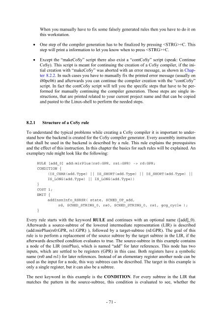
exemplary rule might look like the following:<br />
RULE [add_0] add:mirPlus(rs0:GPR, rs1:GPR) -> rd:GPR;<br />
CONDITION {<br />
(IS_CHAR(add.Type) || IS_SHORT(add.Type) || IS_SHORT(add.Type) ||<br />
IS_LONG(add.Type) || IS_LONG(add.Type))<br />
}<br />
COST 1;<br />
EMIT {<br />
addInsnInfo_RSRSR( state, SCHED_OP_add,<br />
rd, SCHED_STRING_0, rs0, SCHED_STRING_0, rs1, gcg_cycle );<br />
}<br />
Every rule starts with the keyword RULE and continues with an optional name ([add]_0).<br />
Afterwards a source-subtree of the lowered intermediate representation (LIR) is described<br />
(add:mirPlus(rs0:GPR, rs1:GPR) ), followed by a target-subtree (rd:GPR). The goal of this<br />
rule is to per<strong>for</strong>m a replacement of the source subtree by the target subtree in the LIR, if the<br />
afterwards described condition evaluates to true. The source-subtree in this example contains<br />
a node of the LIR (mirPlus), which is named “add” <strong>for</strong> later references. This node has two<br />
inputs, which are settled to be registers (GPR) in this case. Both registers have a symbolic<br />
name (rs0 and rs1) <strong>for</strong> later references. Instead of an elementary register another node can be<br />
used as the input <strong>for</strong> a node, this way subtrees can be described. The target in this example is<br />
only a single register, but it can also be a subtree.<br />
The next keyword in this example is the CONDITION. For every subtree in the LIR that<br />
matches the pattern in the source-subtree, this condition is evaluated to see, whether the<br />
- 71 -


