

Data Sheet - Freescale Semiconductor
Data Sheet - Freescale Semiconductor
Data Sheet - Freescale Semiconductor

Create successful ePaper yourself
Turn your PDF publications into a flip-book with our unique Google optimized e-Paper software.
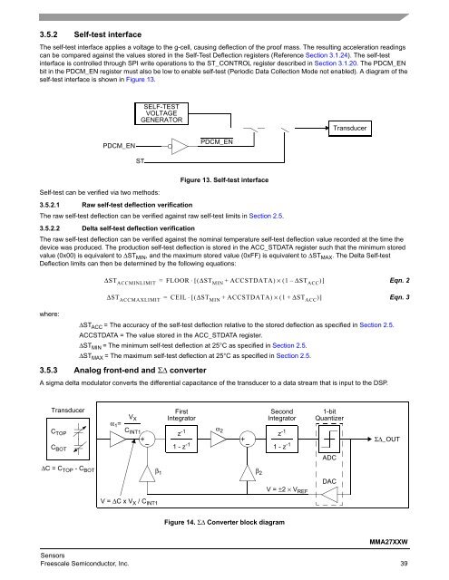
3.5.2 Self-test interface<br />
The self-test interface applies a voltage to the g-cell, causing deflection of the proof mass. The resulting acceleration readings<br />
can be compared against the values stored in the Self-Test Deflection registers (Reference Section 3.1.24). The self-test<br />
interface is controlled through SPI write operations to the ST_CONTROL register described in Section 3.1.20. The PDCM_EN<br />
bit in the PDCM_EN register must also be low to enable self-test (Periodic <strong>Data</strong> Collection Mode not enabled). A diagram of the<br />
self-test interface is shown in Figure 13.<br />
Self-test can be verified via two methods:<br />
Figure 13. Self-test interface<br />
3.5.2.1 Raw self-test deflection verification<br />
The raw self-test deflection can be verified against raw self-test limits in Section 2.5.<br />
3.5.2.2 Delta self-test deflection verification<br />
The raw self-test deflection can be verified against the nominal temperature self-test deflection value recorded at the time the<br />
device was produced. The production self-test deflection is stored in the ACC_STDATA register such that the minimum stored<br />
value (0x00) is equivalent to ΔSTMIN, and the maximum stored value (0xFF) is equivalent to ΔSTMAX. The Delta Self-test<br />
Deflection limits can then be determined by the following equations:<br />
where:<br />
PDCM_EN<br />
SELF-TEST<br />
VOLTAGE<br />
GENERATOR<br />
ST<br />
ΔSTACC = The accuracy of the self-test deflection relative to the stored deflection as specified in Section 2.5.<br />
ACCSTDATA = The value stored in the ACC_STDATA register.<br />
ΔSTMIN = The minimum self-test deflection at 25°C as specified in Section 2.5.<br />
ΔSTMAX = The maximum self-test deflection at 25°C as specified in Section 2.5.<br />
3.5.3 Analog front-end and ΣΔ converter<br />
PDCM_EN<br />
ΔSTACCMINLIMIT = FLOOR ⋅ [ ( ΔSTMIN + ACCSTDATA)<br />
× ( 1 – ΔSTACC) ]<br />
ΔSTACCMAXLIMIT = CEIL ⋅ [ ( ΔSTMIN + ACCSTDATA)<br />
× ( 1 + ΔSTACC) ]<br />
A sigma delta modulator converts the differential capacitance of the transducer to a data stream that is input to the DSP.<br />
Transducer<br />
C TOP<br />
C BOT<br />
ΔC = C TOP - C BOT<br />
α 1=<br />
V X<br />
C INT1<br />
β 1<br />
V = ΔC x V X / C INT1<br />
First<br />
Integrator<br />
z -1<br />
1 - z -1<br />
α 2<br />
Second<br />
Integrator<br />
Figure 14. ΣΔ Converter block diagram<br />
1-bit<br />
Quantizer<br />
Transducer<br />
Eqn. 2<br />
Eqn. 3<br />
MMA27XXW<br />
Sensors<br />
<strong>Freescale</strong> <strong>Semiconductor</strong>, Inc. 39<br />
β 2<br />
z -1<br />
1 - z -1<br />
V = ±2 × V REF<br />
ADC<br />
DAC<br />
ΣΔ_OUT


