

Data Sheet - Freescale Semiconductor
Data Sheet - Freescale Semiconductor
Data Sheet - Freescale Semiconductor

You also want an ePaper? Increase the reach of your titles
YUMPU automatically turns print PDFs into web optimized ePapers that Google loves.
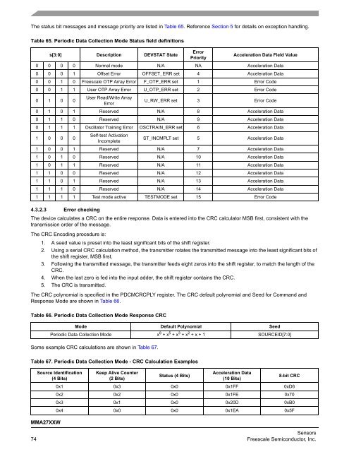
The status bit messages and message priority are listed in Table 65. Reference Section 5 for details on exception handling.<br />
Table 65. Periodic <strong>Data</strong> Collection Mode Status field definitions<br />
s[3:0] Description DEVSTAT State<br />
Error<br />
Priority<br />
Acceleration <strong>Data</strong> Field Value<br />
0 0 0 0 Normal mode N/A NA Acceleration <strong>Data</strong><br />
0 0 0 1 Offset Error OFFSET_ERR set 4 Acceleration <strong>Data</strong><br />
0 0 1 0 <strong>Freescale</strong> OTP Array Error F_OTP_ERR set 1 Error Code<br />
0 0 1 1 User OTP Array Error U_OTP_ERR set 2 Error Code<br />
0 1 0 0<br />
User Read/Write Array<br />
Error<br />
U_RW_ERR set 3 Error Code<br />
0 1 0 1 Reserved N/A 8 Acceleration <strong>Data</strong><br />
0 1 1 0 Reserved N/A 9 Acceleration <strong>Data</strong><br />
0 1 1 1 Oscillator Training Error OSCTRAIN_ERR set 6 Acceleration <strong>Data</strong><br />
1 0 0 0<br />
Self-test Activation<br />
Incomplete<br />
ST_INCMPLT set 5 Acceleration <strong>Data</strong><br />
1 0 0 1 Reserved N/A 7 Acceleration <strong>Data</strong><br />
1 0 1 0 Reserved N/A 10 Acceleration <strong>Data</strong><br />
1 0 1 1 Reserved N/A 11 Acceleration <strong>Data</strong><br />
1 1 0 0 Reserved N/A 12 Acceleration <strong>Data</strong><br />
1 1 0 1 Reserved N/A 13 Acceleration <strong>Data</strong><br />
1 1 1 0 Reserved N/A 14 Acceleration <strong>Data</strong><br />
1 1 1 1 Test mode active TESTMODE set 15 Error Code<br />
4.3.2.3 Error checking<br />
The device calculates a CRC on the entire response. <strong>Data</strong> is entered into the CRC calculator MSB first, consistent with the<br />
transmission order of the message.<br />
The CRC Encoding procedure is:<br />
1. A seed value is preset into the least significant bits of the shift register.<br />
2. Using a serial CRC calculation method, the transmitter rotates the transmitted message into the least significant bits of<br />
the shift register, MSB first.<br />
3. Following the transmitted message, the transmitter feeds eight zeros into the shift register, to match the length of the<br />
CRC.<br />
4. When the last zero is fed into the input adder, the shift register contains the CRC.<br />
5. The CRC is transmitted.<br />
The CRC polynomial is specified in the PDCMCRCPLY register. The CRC default polynomial and Seed for Command and<br />
Response Mode are shown in Table 66.<br />
Table 66. Periodic <strong>Data</strong> Collection Mode Response CRC<br />
Some example CRC calculations are shown in Table 67.<br />
MMA27XXW<br />
Mode Default Polynomial Seed<br />
Periodic <strong>Data</strong> Collection Mode x 8 + x 5 + x 3 + x 2 + x + 1 SOURCEID[7:0]<br />
Table 67. Periodic <strong>Data</strong> Collection Mode - CRC Calculation Examples<br />
Source Identification<br />
(4 Bits)<br />
Keep Alive Counter<br />
(2 Bits)<br />
Status (4 Bits)<br />
Acceleration <strong>Data</strong><br />
(10 Bits)<br />
8-bit CRC<br />
0x1 0x3 0x0 0x1FF 0xD6<br />
0x2 0x2 0x0 0x1FE 0x70<br />
0x3 0x1 0x0 0x20D 0xB0<br />
0x4 0x0 0x0 0x1EA 0x5F<br />
Sensors<br />
74 <strong>Freescale</strong> <strong>Semiconductor</strong>, Inc.


