- Page 2 and 3:
© 2009 European Nuclear Society Ru
- Page 4 and 5:
RESEARCH REACTOR COALITIONS - SECON
- Page 6 and 7:
- Eastern European Research Reactor
- Page 8 and 9:
ut a comprehensive alignment of tec
- Page 10 and 11:
EERRI will be launched. As noted ab
- Page 12 and 13:
Nuclear material in the form of hig
- Page 14 and 15:
The GTRI domestic radiological mate
- Page 16 and 17:
2. State of the art For fuel plate
- Page 18 and 19:
It is known since the early days of
- Page 20 and 21:
End of 2008 first DU-8wt.%Mo (deple
- Page 22 and 23:
References [1] D. AB. Robinson et a
- Page 24 and 25:
• CNEA have been working in the f
- Page 26 and 27:
O 75 Bignan.doc - DI - 1 / 10 20/02
- Page 28 and 29:
O 75 Bignan.doc - DI - 3 / 10 20/02
- Page 30 and 31:
O 75 Bignan.doc - DI - 5 / 10 20/02
- Page 32 and 33:
O 75 Bignan.doc - DI - 7 / 10 20/02
- Page 34 and 35:
O 75 Bignan.doc - DI - 9 / 10 20/02
- Page 36 and 37:
THE EAST EUROPEAN RESEARCH REACTOR
- Page 38 and 39:
namely Jozef Stefan Institute TRIGA
- Page 40 and 41:
Information and organizational issu
- Page 42 and 43:
Action Item Table 3. Description (t
- Page 44 and 45:
Table 6. Materials/fuel test experi
- Page 46 and 47:
In a recent development, it should
- Page 48 and 49:
1. Introduction: a renewed context
- Page 50 and 51:
interaction, close retention of fis
- Page 52 and 53:
3.3 Reference concept and alternati
- Page 54 and 55:
changes can be caused by void swell
- Page 56 and 57:
For its manufacturing, an additiona
- Page 58 and 59:
minor actinides (MA) considered as
- Page 60 and 61:
In France, the decision to build a
- Page 62 and 63:
eactors (HFR, OSIRIS and then JHR)
- Page 64 and 65:
DECOMMISSIONING PROGRESS OF THE DOU
- Page 66 and 67:
DECOMMISSIONING PROGRESS OF THE DOU
- Page 68 and 69:
DECOMMISSIONING PROGRESS OF THE DOU
- Page 70 and 71:
SECURITY OF SUPPLY FOR FISSION MEDI
- Page 72 and 73:
But the worst crisis developed by e
- Page 74 and 75:
IRE and COVIDEN are following close
- Page 76 and 77:
Fig 1. Design of the core and refle
- Page 78 and 79:
Table 3: Set of detailed fuel funct
- Page 80 and 81:
For the thermal-mechanical analysis
- Page 82 and 83:
Behaviour under conditions represen
- Page 84 and 85:
6. References [1] - MC. Anselmet, G
- Page 86 and 87:
2. Advanced nuclear fuel cycles The
- Page 88 and 89:
3.3 India In addition to the ration
- Page 90 and 91:
Session II Fuel Development 90 of 4
- Page 92 and 93:
1. Introduction Since 1957, date of
- Page 94 and 95:
A 3.1. Place a boron insert in a hi
- Page 96 and 97:
Finally, a new tool was defined and
- Page 98 and 99:
the end user (CEA), to define the f
- Page 100 and 101:
Previous papers discussed character
- Page 102 and 103:
(a) (b) (c) (d) (e) (f) (g) (h) (i)
- Page 104 and 105:
The results of a third reported irr
- Page 106 and 107:
In order to reproduce the heat tran
- Page 108 and 109:
25 OXIDE THICKNESS 20 Kim et al pH=
- Page 110 and 111:
Heavy ion irradiation of UMo7/Al fu
- Page 112 and 113:
For the lowest flux values tested d
- Page 114 and 115:
127 I beam 127 I beam 0 5 10 15 20
- Page 116 and 117:
Weight fractions (%) U(α) UO 2 γU
- Page 118 and 119:
activities to meet the need. The co
- Page 120 and 121:
Heat capacity Information Thermal c
- Page 122 and 123:
Decision point Activity Phase 2: Fu
- Page 124 and 125:
IRIS PROGRAM: IRIS4 FIRST RESULTS F
- Page 126 and 127:
The main characteristics of the IRI
- Page 128 and 129:
4. In-pool plate thickness measurem
- Page 130 and 131:
At that stage of IRIS4 irradiation
- Page 132 and 133:
extrapolated thermal property value
- Page 134 and 135:
optical microscope, acoustic emissi
- Page 136 and 137:
CD WIRES AS BURNABLE POISON FOR THE
- Page 138 and 139:
Figure 1. MCNP geometry model of fu
- Page 140 and 141:
considered carefully: (i) maintain
- Page 142 and 143:
discussed and validated together, k
- Page 144 and 145:
The as-fabrication Si contents in t
- Page 146 and 147:
uniform Si diffusion and consequent
- Page 148 and 149:
Recently, fuel relocation induced b
- Page 150 and 151:
characteristics of ILs obtained in
- Page 152 and 153:
- Type 2 (Si content ≥ 5 wt%) : c
- Page 154 and 155:
4. Discussion The main contribution
- Page 156 and 157:
METHODS OF INCREASING THE URANIUM C
- Page 158 and 159:
• strength properties of Zr-1% Nb
- Page 160 and 161:
4. References 1. Birzhevoy G.A., Ka
- Page 162 and 163:
Dispersion fuel Monolithic fuel ATR
- Page 164 and 165:
− because of its Newtonian charac
- Page 166 and 167:
Session III Back-end 166 of 455
- Page 168 and 169:
Fig.1. The transfer hall (left in c
- Page 170 and 171:
The shipment included all the SNF f
- Page 172 and 173:
FRESH AND SPENT NUCLEAR FUEL REPATR
- Page 174 and 175:
modifications, spent fuel inspectio
- Page 176 and 177:
The shipment cleared Romanian Custo
- Page 178 and 179:
steel are chosen as effective gamma
- Page 180 and 181:
Fig 3. Long lived nuclides radioact
- Page 182 and 183:
Session IV Innovative Methods in Re
- Page 184 and 185:
Lower Gr-reflector Al-clad Upper Gr
- Page 186 and 187:
All described fuel elements were ca
- Page 188 and 189:
ANALYSIS OF NEW SAFETY CRITERIA FOR
- Page 190 and 191:
3.2 Strain limit The value of 3.65%
- Page 192 and 193:
The comparison between clad tempera
- Page 194 and 195:
VALIDATION OF PLTEMP/ANL V3.6 CODE
- Page 196 and 197:
ΔT p 0.0234 2 ⎪⎧ q[W/cm ] ⎪
- Page 198 and 199:
Table II. Hot Channel Factors for B
- Page 200 and 201:
for the U-8Mo fuel meat [5]. The po
- Page 202 and 203:
correlation of Dittus-Boelter; the
- Page 204 and 205:
ROLE OF RELAP/SCDAPSIM IN RESEARCH
- Page 206 and 207:
ROLE OF RELAP/SCDAPSIM IN RESEARCH
- Page 208 and 209:
ROLE OF RELAP/SCDAPSIM IN RESEARCH
- Page 210 and 211:
ROLE OF RELAP/SCDAPSIM IN RESEARCH
- Page 212 and 213: SEVERE REACTIVITY INJECTION ACCIDEN
- Page 214 and 215: expansion and steam formation were
- Page 216 and 217: 3 Conclusion Since a few years, IRS
- Page 218 and 219: analysis procedure (ENAA) except vi
- Page 220 and 221: References Briesmeister, J.F., 2000
- Page 222 and 223: Fig. 1 A geometric diagram of NIRR-
- Page 224 and 225: Fuel plate temperatures during oper
- Page 226 and 227: the primary circuit in the central
- Page 228 and 229: Fig. 3: Surface temperature over th
- Page 230 and 231: [4] “Test Irradiations of Full Si
- Page 232 and 233: The core is made of 1488 stainless
- Page 234 and 235: 4. Commissioning the facility for t
- Page 236 and 237: ESTABLISHMENT OF A SINGLE-CRYSTAL F
- Page 238 and 239: were provided to MU and INL for thi
- Page 240 and 241: concrete covered with sheets of 1.2
- Page 242 and 243: USE OF FISSION RADIATION IN LIFE SC
- Page 244 and 245: Fig. 3. Scan of an etch track film
- Page 246 and 247: Summary The unique fission neutron
- Page 248 and 249: 2. Methods 2.1 Reactor produced rad
- Page 250 and 251: 3.2 Viability studies The results o
- Page 252 and 253: DESIGN OF A FLOWING-NAK EXPERIMENTA
- Page 254 and 255: 4. Containment rig and sample-holde
- Page 256 and 257: 7. Electrical heater The external h
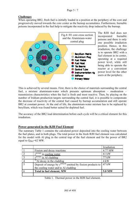
- Page 258 and 259: Page 1 / 7 EVITA: a semi-open loop
- Page 260 and 261: Page 3 / 7 Fig.1: EVITA fuel Genera
- Page 264 and 265: Page 7 / 7 References: [1] M.C. Ans
- Page 266 and 267: Nuclear Research Institutes, and so
- Page 268 and 269: According to the latest IAEA inform
- Page 270 and 271: 18. May Training of operating perso
- Page 272 and 273: 2.1 Irradiation Facilities Brief te
- Page 274 and 275: 3.1 Detection limits Although it is
- Page 276 and 277: PARTIAL DISMANTLING OF RESEARCH REA
- Page 278 and 279: • Core - liable to full scale rep
- Page 280 and 281: • Necessary individual dosimetry
- Page 282 and 283: SILICON DOPING AT FRM II H. GERSTEN
- Page 284 and 285: The resulting neutron flux density
- Page 286 and 287: 4. References [1] Wagner F.M., Knes
- Page 288 and 289: The choice of fuel base and solutio
- Page 290 and 291: 3.3 Increasing power beyond current
- Page 292 and 293: A COATING TO PROTECT SPENT ALUMINIU
- Page 294 and 295: The treatment consisted of simple i
- Page 296 and 297: 5. Conclusions 1. Immersion of AA 1
- Page 298 and 299: KEEPING AGING RESEARCH REACTORS IN
- Page 300 and 301: inspected in presence of an expert
- Page 302 and 303: After the inspection was finished,
- Page 304 and 305: 1 A STRATEGY FOR MANAGING AGEING CO
- Page 306 and 307: 3 2. With the aluminium-clad HEU fu
- Page 308 and 309: 5 The pool and the support structur
- Page 310 and 311: Fig.2. Reflector element of JRR-4.
- Page 312 and 313:
Dimensional change (%) 0.6 0.5 0.4
- Page 314 and 315:
SAFETY CONSIDERATIONS FOR CORE MANA
- Page 316 and 317:
3 3. Core operation and monitoring
- Page 318 and 319:
5 temperature, etc.). Effective sec
- Page 320 and 321:
1436 keV, Cs 138 1369 keV, Na 24 2.
- Page 322 and 323:
compared with that of the delayed n
- Page 324 and 325:
AD-HOC AND PREVENTATIVE MAINTENANCE
- Page 326 and 327:
Page 3 of 7 3. SAFARI-1OPERATIONAL
- Page 328 and 329:
Page 5 of 7 programs for instrument
- Page 330 and 331:
Page 7 of 7 DATE DESCRIPTION DATE D
- Page 332 and 333:
MICROSTRUCTURAL ANALYSIS OF MTR FUE
- Page 334 and 335:
In sample S3, similar zones could b
- Page 336 and 337:
increased temperature, the solid st
- Page 338 and 339:
Figure 8 BEI images covering Sample
- Page 340 and 341:
660 °C, but since in the former me
- Page 342 and 343:
support. Both Governments have eval
- Page 344 and 345:
• Removal of sludge from the SNF
- Page 346 and 347:
UPGRADED REACTOR SYSTEMS FOR ENHANC
- Page 348 and 349:
Parameter HEU LEU a 6.0x10 -5 (°K)
- Page 350 and 351:
From 1992 until 2005 the TRIGA-SSR
- Page 352 and 353:
Figure9 - Dependency between reacto
- Page 354 and 355:
URANIUM CONTAMINATION IN PRIMARY CI
- Page 356 and 357:
1.00E+06 1.00E+05 Volume activity (
- Page 358 and 359:
6. Acknowledgement This work was pe
- Page 360 and 361:
2. Steady State Thermal Hydraulic A
- Page 362 and 363:
in the scram, and the respective re
- Page 364 and 365:
CORROSION BEHAVIOR OF ALUMINIUM ALL
- Page 366 and 367:
3.2. Pitting corrosion of 1050 and
- Page 368 and 369:
4. Discussions This study shown tha
- Page 370 and 371:
The Steady State core was fully con
- Page 372 and 373:
0.E+00 2.E+06 1.40E+07 2.E+06 1.20E
- Page 374 and 375:
SYNTHESIS AND CHARACTERIZATION OF G
- Page 376 and 377:
0 2 4 6 8 10 120 1,2 100 1,0 80 70
- Page 378 and 379:
Element, Wt %, At %, K‐Ratio, Z,
- Page 380 and 381:
U/cc, but the target uranium densit
- Page 382 and 383:
Fig. 5 Macroscopic cutting view (x
- Page 384 and 385:
SELF-ASSESSMENT OF APPLICATION OF T
- Page 386 and 387:
2. The Code of Conduct on the Safet
- Page 388 and 389:
For emergency preparedness, conside
- Page 390 and 391:
inside of a compaction die by blowi
- Page 392 and 393:
Fig. 4. A compacted and sintered lu
- Page 394 and 395:
THE MANAGEMENT SYSTEM EVOLUTION OF
- Page 396 and 397:
etween CRPq specific process and IP
- Page 398 and 399:
aspect audits, mainly in relation t
- Page 400 and 401:
1 2 3 4 5 6 7 8 9 A B C D E F G H F
- Page 402 and 403:
MCNP5 is capable of calculating ter
- Page 404 and 405:
Similar to the case of stainless st
- Page 406 and 407:
LEU FUEL DISPOSITION AT WWR-M REACT
- Page 408 and 409:
Tested fuel assembles are load in t
- Page 410 and 411:
The PNPI experience of tests with W
- Page 412 and 413:
CURRENT UTILIZATION AND LONG TERM S
- Page 414 and 415:
Uusimaa hospital district decided t
- Page 416 and 417:
FiR 1 has an important regional rol
- Page 418 and 419:
STUDYING OF INFLUENCE OF A NEUTRON
- Page 420 and 421:
Definition of crystal structure and
- Page 422 and 423:
Microhardness measurement shows, th
- Page 424 and 425:
THE SPENT FUEL STORAGE AT THE DALAT
- Page 426 and 427:
2. Interim storage of spent fuel On
- Page 428 and 429:
A rotating bridge crane of 3.6-ton
- Page 430 and 431:
In order to investigate the perform
- Page 432 and 433:
(a) (b) Fig. 2. (a) low and (b) hig
- Page 434 and 435:
(a) (b) (c) (d) (e) (f) Fig. 5. TEM
- Page 436 and 437:
Spot Al Si Mo U Zr G 90.6 7.8 0.6 0
- Page 438 and 439:
volume in the material, which affec
- Page 440 and 441:
THE STEREOMETRIC ANALYSIS OF GAS PO
- Page 442 and 443:
of the crack of pillowing). It show
- Page 444 and 445:
One gets the impression that during
- Page 446 and 447:
switch from a fast to a thermal spe
- Page 448 and 449:
He production to fission ratio vs t
- Page 450 and 451:
INSPECTION EXPERIENCE WITH IEA-R1 S
- Page 452 and 453:
camera system, received from IAEA i
- Page 454:
core in the beginning 2007 (IEA-174