ABB i-Bus® EIB/KNX ABB Powernet EIB/KNX
ABB i-Bus® EIB/KNX ABB Powernet EIB/KNX
ABB i-Bus® EIB/KNX ABB Powernet EIB/KNX

Create successful ePaper yourself
Turn your PDF publications into a flip-book with our unique Google optimized e-Paper software.
<strong>ABB</strong> i-bus ® <strong>EIB</strong>/<strong>KNX</strong><br />
<strong>ABB</strong> <strong>Powernet</strong> <strong>EIB</strong>/<strong>KNX</strong><br />
LEANtouch (monochrome),<br />
SMARTtouch (monochrome, colour)<br />
Type: 6x36/30M…, 6x36/100x…, 6x36/100CB…<br />
Functional description: Touch surfaces<br />
(Homepage)<br />
Homepage<br />
The start page of the panel is page 1<br />
by default but each of the 21 other pages<br />
can be declared the start page. If<br />
a submenu (pages 2 to 21, system,<br />
“Extras”, alarm control unit or alarm<br />
messages) has been retrieved via the<br />
touch surfaces, the panel changes<br />
back automatically to the last operator<br />
page after a long period of inactivity.<br />
To do so, the parameter “Page automatically<br />
in the foreground” must be<br />
activated. The preset delay after which<br />
the panel displays the start page is<br />
1:01 min and is adjustable.<br />
Note:<br />
If you do not require the panel to revert<br />
back automatically to the start<br />
page, you must ensure that all the hyperlink<br />
functions concur with this i.e.<br />
you cannot create a page from which<br />
the user cannot access the previous<br />
page or the start page. The preview<br />
window of the panel software offers<br />
the opportunity to check the configuration<br />
of the various pages and their hyperlink<br />
functions.<br />
Hyperlink functions to submenus and<br />
operator functions can also be created<br />
on the start page itself.<br />
Monitoring function<br />
(only SMARTtouch)<br />
A signalling function can also be retrieved<br />
via any touch surface on the<br />
panel. To do so, the touch surface<br />
must be assigned a hyperlink function.<br />
“Alarm control unit” must then be selected<br />
in the hyperlink parameter.<br />
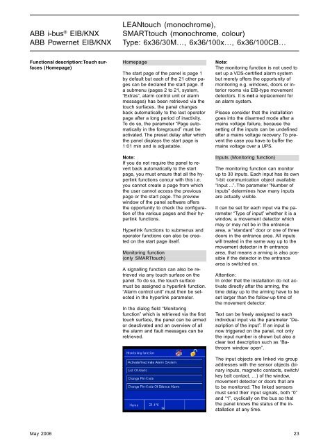
In the dialog field “Monitoring<br />
function” which is retrieved via the first<br />
touch surface, the panel can be armed<br />
or deactivated and an overview of all<br />
the alarm and fault messages can be<br />
retrieved.<br />
Note:<br />
The monitoring function is not used to<br />
set up a VDS-certified alarm system<br />
but merely offers the opportunity of<br />
monitoring e.g. windows, doors or interior<br />
rooms via <strong>EIB</strong>-type movement<br />
detectors. It is not a replacement for<br />
an alarm system.<br />
Please consider that the installation<br />
goes into the disarmed mode after a<br />
mains voltage failure, because the<br />
setting of the inputs can be undefined<br />
after a mains voltage recovery. To prevent<br />
the case you have to buffer the<br />
mains voltage over a UPS.<br />
Inputs (Monitoring function)<br />
The monitoring function can monitor<br />
up to 30 inputs. Each input has its own<br />
1-bit communication object available<br />
“Input ...”. The parameter “Number of<br />
inputs” determines how many inputs<br />
are actually visible.<br />
It can be set for each input via the parameter<br />
“Type of input” whether it is a<br />
window, a movement detector which<br />
may or may not be in the entrance<br />
area, a “standard” door or one of three<br />
doors in the entrance area. All inputs<br />
will treated in the same way up to the<br />
movement detector in th entrance<br />
area, that means a arming is also possible<br />
if the detector in the entrance<br />
area is switched on.<br />
Attention:<br />
In order that the installation do not activate<br />
directly after the arming, the<br />
time delay up to the arming have to be<br />
set larger than the follow-up time of<br />
the movement detector.<br />
Text can be freely assigned to each<br />
individual input via the parameter “Description<br />
of the input”. If an input is<br />
now triggered on the panel, not only<br />
the input number is shown but also a<br />
clear text description such as “Bathroom<br />
window open”.<br />
The input objects are linked via group<br />
addresses with the sensor objects (binary<br />
inputs, magnetic contacts, switch/<br />
key bolt contact, …) of the window,<br />
movement detector or doors that are<br />
to be monitored. The linked sensors<br />
must send their input signals, both “0”<br />
and “1”, cyclically on the bus so that<br />
the panel knows the status of the installation<br />
at any time.<br />
May 2006 23