ABB i-Bus® EIB/KNX ABB Powernet EIB/KNX
ABB i-Bus® EIB/KNX ABB Powernet EIB/KNX
ABB i-Bus® EIB/KNX ABB Powernet EIB/KNX

You also want an ePaper? Increase the reach of your titles
YUMPU automatically turns print PDFs into web optimized ePapers that Google loves.
<strong>ABB</strong> i-bus ® <strong>EIB</strong>/<strong>KNX</strong><br />
<strong>ABB</strong> <strong>Powernet</strong> <strong>EIB</strong>/<strong>KNX</strong><br />
LEANtouch (monochrome),<br />
SMARTtouch (monochrome, colour)<br />
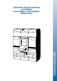
Type: 6x36/30M…, 6x36/100x…, 6x36/100CB…<br />
so, a 2-byte temperature value must<br />
be sent to the object “Base setpoint”.<br />
The setpoint temperature can be<br />
changed manually via the rocker buttons<br />
on the panel display. The parameters<br />
“Area for manual setpoint setting”,<br />
“Maximum increasing of setpoint<br />
at heating” and “Maximum lowering of<br />
control value at cooling” determine<br />
the scope for modifying the setpoint. If<br />
a new telegram is sent to the communication<br />
object “Base setpoint” after a<br />
manual setpoint adjustment, the manual<br />
setpoint adjustment can also be<br />
reversed.<br />
Heating/cooling<br />
To be able to address the various controller<br />
types for heating or cooling<br />
mode, the room thermostat can be parameterised<br />
as a continuous or switching<br />
controller. In the case of a switching<br />
controller, it is possible to choose<br />
between a PWM controller (“PI controller”)<br />
and a “Two-position controller”.<br />
In the case of a continuous control response<br />
and a switching PWM controller,<br />
the preset control parameters regarding<br />
the installation type of the<br />
heating or air conditioning system can<br />
be used. If other control parameters<br />
are needed, they can be set individually<br />
via the free parameterisation<br />
option. This option should only be<br />
used if the user has sufficient experience<br />
in control technology.<br />
The continuous controller sends its<br />
control value to a 1-byte object. Electromotive<br />
or electrothermal drives<br />
which are connected to heating actuators<br />
with PWM control can thus be<br />
controlled.<br />
To prevent unnecessary bus loads, it<br />
is possible to set by how much the<br />
control value must change in order to<br />
be sent on the bus. The setting is carried<br />
out as a percentage. The sending<br />
of the control value is preset by a cyclic<br />
period, provided it has not been<br />
modified. This cycle time should not<br />
be set too low (e.g. every 10 min).<br />
In the case of a switching PWM controller,<br />
the output value of the controller<br />
(0...255) is converted into an ON/OFF<br />
ratio. If e.g. a control value of 70%<br />
should be issued, the ON time is 7<br />
min and the OFF time is 3 min at a<br />
preset cycle time of 10 min. The dynamic<br />
range can also be limited in the<br />
same way as a continuous controller.<br />
The parameters “PWM cycle is 0% up<br />
to control value” and “PWM cycle is<br />
100% up to control value” are used for<br />
this purpose. If e.g. a maximum control<br />
value of 80% is set, the controller automatically<br />
sends the value 255 when<br />
a control value of 204 is exceeded.<br />
(See also the diagram below)<br />
To optimise the control characteristics<br />
of the heating or cooling system, the<br />
“Cycle time of the control value” can<br />
be set. To set the correct cycle time,<br />
the type of heating or cooling as well<br />
as the valve drive used should be taken<br />
into account. The following recommendations<br />
can be used:<br />
a)Electrothermal valve drive:<br />
To fully open an electrothermal val-<br />
Output<br />
Control value<br />
100%<br />
80%<br />
20%<br />
0<br />
0<br />
20% 80% 100%<br />
Internal control<br />
value of cont.<br />
controller<br />
May 2006 65