

Download RoboCylinder Servo RCS Controller ... - pulsar.com.tr
Download RoboCylinder Servo RCS Controller ... - pulsar.com.tr
Download RoboCylinder Servo RCS Controller ... - pulsar.com.tr

You also want an ePaper? Increase the reach of your titles
YUMPU automatically turns print PDFs into web optimized ePapers that Google loves.
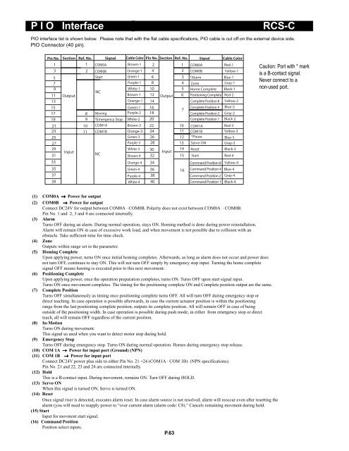
P I O Interface<br />
<s<strong>tr</strong>ong>RCS</s<strong>tr</strong>ong>-C<br />
PIO interface list is shown below. Please note that with the flat cable specifications, PIO cable is cut off on the external device side.<br />
PIO Connector (40 pin).<br />
Pin No. Section Ref. No. Signal Cable Color Pin No. Section Ref. No. Signal Cable Color<br />
1<br />
3<br />
1<br />
2<br />
COM0A<br />
COM0B<br />
Brown-1<br />
Orange-1<br />
2<br />
4<br />
1<br />
2<br />
COM0A<br />
COM0B<br />
Red-1<br />
Yellow-1<br />
5<br />
Start<br />
Green-1 6<br />
3 *Alarm<br />
Blue-1<br />
7<br />
Purple-1 8<br />
4 Zone<br />
Gray-1<br />
9<br />
White-1 10<br />
5 Home Complete Black-1<br />
NC<br />
11 Output<br />
Brown-1 12 Output 6 Positioning Complete Red-2<br />
13<br />
Orange-1 14<br />
Complete Position 8 Yellow-2<br />
15<br />
Green-1 16<br />
Complete Position 4 Blue-2<br />
7<br />
17<br />
8 Moving<br />
Purple-2 18<br />
Complete Position 2 Gray-2<br />
19<br />
21<br />
23<br />
25<br />
27<br />
9<br />
10<br />
11<br />
*Emergency Stop<br />
COM1A<br />
COM1B<br />
White-2<br />
Brown-3<br />
Orange-3<br />
Green-3<br />
Purple-3<br />
20<br />
22<br />
24<br />
26<br />
28<br />
10<br />
11<br />
12<br />
13<br />
Complete Position 1<br />
COM1A<br />
COM1B<br />
*Pause<br />
<s<strong>tr</strong>ong>Servo</s<strong>tr</strong>ong> ON<br />
Black-2<br />
Red-3<br />
Yellow-3<br />
Blue-3<br />
Gray-3<br />
29<br />
White-3 30<br />
14 Reset<br />
Black-3<br />
Input<br />
Input<br />
31<br />
NC<br />
Brown-4 32<br />
15 Start<br />
Red-4<br />
33<br />
35<br />
37<br />
39<br />
Orange-4<br />
Green-4<br />
Purple-4<br />
White-4<br />
34<br />
36<br />
38<br />
40<br />
16<br />
Command Position 8<br />
Command Position 4<br />
Command Position 2<br />
Command Position 1<br />
Yellow-4<br />
Blue-4<br />
Gray-4<br />
Black-4<br />
Caution: Port with * mark<br />
is a B-contact signal.<br />
Never connect to a<br />
non-used port.<br />
(1) COM0A → Power for output<br />
(2) COM0B → Power for output<br />
Connect DC24V for output between COM0A · COM0B. Polarity does not exist between COM0A · COM0B.<br />
Pin No. 1 and 2, 3 and 4 are connected internally.<br />
(3) Alarm<br />
Turns OFF during an alarm. During normal operation, stays ON. Homing method is done during power reinstallation.<br />
Alarm will remain ON in case of excessive work load, and when movement is not possible due to collision with an<br />
obstacle. Take sufficient time for time check.<br />
(4) Zone<br />
Outputs within range set in the parameter.<br />
(5) Homing Complete<br />
Upon applying power, turns ON once initial homing <s<strong>tr</strong>ong>com</s<strong>tr</strong>ong>pletes. Afterwards, as long as alarm does not occur and power does<br />
not turn OFF, continues to stay ON. This will not turn OFF simply by emergency stop input. Turning the home <s<strong>tr</strong>ong>com</s<strong>tr</strong>ong>plete<br />
signal OFF means homing is executed prior to this next movement:<br />
(6) Positioning Complete<br />
Upon applying power, once the operation preparation <s<strong>tr</strong>ong>com</s<strong>tr</strong>ong>pletes, turns ON. Turns OFF upon start signal input.<br />
Turns ON once movement <s<strong>tr</strong>ong>com</s<strong>tr</strong>ong>pletes. The timing for the positioning <s<strong>tr</strong>ong>com</s<strong>tr</strong>ong>plete ON and Complete position output are the same.<br />
(7) Complete Position<br />
Turns OFF simultaneously as timing once positioning <s<strong>tr</strong>ong>com</s<strong>tr</strong>ong>plete turns OFF. All will turn OFF during emergency stop or<br />
direct teaching. In case operation is possible afterwards, in case the current actuator position is within the positioning<br />
range from the last positioning <s<strong>tr</strong>ong>com</s<strong>tr</strong>ong>plete position, outputs its <s<strong>tr</strong>ong>com</s<strong>tr</strong>ong>plete position. All will remain OFF in case of being<br />
outside of the positioning width. In case operation is possible during push mode, in either from emergency stop or direct<br />
teach, all will remain OFF regardless of the current position.<br />
(8) In-Motion<br />
Turns ON during movement.<br />
This signal us used when you want to detect motor stop during hold.<br />
(9) Emergency Stop<br />
Turns OFF during emergency stop. Turns ON during normal operation. Homes during emergency stop release.<br />
(10) COM 1A → Power for input port (Ground) (NPN)<br />
(11) COM 1B → Power for input port<br />
Connect DC24V power plus side to either Pin No. 21 ~24 (COM1A · COM 1B) (NPN specifications).<br />
Pin No. 21 and 22, 23 and 24 are connected internally.<br />
(12) Hold<br />
This is a B-contact input. During movement, remains ON. Turn OFF during HOLD.<br />
(13) <s<strong>tr</strong>ong>Servo</s<strong>tr</strong>ong> ON<br />
When this signal is turned ON, <s<strong>tr</strong>ong>Servo</s<strong>tr</strong>ong> is turned ON.<br />
(14) Reset<br />
Once signal riser is detected, executes alarm reset. In case alarm source is not resolved, alarm will reoccur even after resetting the<br />
alarm (you will need to reapply power to “over current alarm (alarm code: C8).” Cancels remaining movment during hold.<br />
(15) Start<br />
Input for movment start signal.<br />
(16) Command Position<br />
Position select inputs.<br />
P.63


