Rotational Raman scattering in the Earth's atmosphere ... - SRON
Rotational Raman scattering in the Earth's atmosphere ... - SRON
Rotational Raman scattering in the Earth's atmosphere ... - SRON

You also want an ePaper? Increase the reach of your titles
YUMPU automatically turns print PDFs into web optimized ePapers that Google loves.
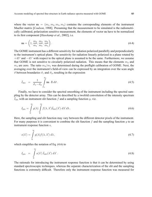
Accurate model<strong>in</strong>g of spectral f<strong>in</strong>e-structure <strong>in</strong> Earth radiance spectra measured with GOME 83<br />
where <strong>the</strong> vector m = (m 1 ,m 2 ,m 3 ,m 4 ) conta<strong>in</strong>s <strong>the</strong> correspond<strong>in</strong>g elements of <strong>the</strong> <strong>in</strong>strument<br />
Mueller matrix [Coulson, 1988]. Presum<strong>in</strong>g that <strong>the</strong> measurement to be simulated is <strong>the</strong> radiometrically<br />
calibrated, polarization sensitive measurement, <strong>the</strong> elements of vector m have to be normalized<br />
to its first component [Hasekamp et al., 2002], i.e.<br />
(<br />
m = 1, m 2<br />
, m 3<br />
, m )<br />
4<br />
. (4.4)<br />
m 1 m 1 m 1<br />
The GOME <strong>in</strong>strument has a different sensitivity for radiation polarized parallelly and perpendicularly<br />
to <strong>the</strong> <strong>in</strong>strument’s optical plane. The sensitivity for radiation l<strong>in</strong>early polarized <strong>in</strong> a plane rotated by<br />
+45 ◦ and −45 ◦ with respect to <strong>the</strong> optical plane is assumed to be <strong>the</strong> same. Fur<strong>the</strong>rmore, we assume<br />
that GOME is not sensitive to circularly polarized radiation. This means that <strong>the</strong> elements m 3 and<br />
m 4 are zero. The ratio m 2 /m 1 was determ<strong>in</strong>ed dur<strong>in</strong>g <strong>the</strong> preflight calibration of GOME. Next, <strong>the</strong><br />
averag<strong>in</strong>g over <strong>the</strong> <strong>in</strong>strument’s field-of-view can be expressed by an <strong>in</strong>tegration over <strong>the</strong> scan angle<br />
ϑ between boundaries ϑ 1 and ϑ 2 , result<strong>in</strong>g <strong>in</strong> <strong>the</strong> expression<br />
Ī det =<br />
∫ϑ 2<br />
1<br />
ϑ 1 −ϑ 2<br />
ϑ 1<br />
m · I dϑ . (4.5)<br />
F<strong>in</strong>ally, we have to consider <strong>the</strong> spectral smooth<strong>in</strong>g of <strong>the</strong> <strong>in</strong>strument <strong>in</strong>clud<strong>in</strong>g <strong>the</strong> spectral sampl<strong>in</strong>g<br />
by <strong>the</strong> detector array. This can be described by a twofold convolution of <strong>the</strong> <strong>in</strong>tensity spectrum<br />
Ī det with an <strong>in</strong>strument slit function f and a sampl<strong>in</strong>g function g, viz.<br />
I pix =<br />
∫ ∞<br />
g(λ)<br />
∫ ∞<br />
f(λ,λ ′ )Īdet(λ ′ ) dλ ′ dλ . (4.6)<br />
0<br />
0<br />
Here, <strong>the</strong> sampl<strong>in</strong>g and slit function may vary between <strong>the</strong> different detector pixels of <strong>the</strong> <strong>in</strong>strument.<br />
For many purposes it is convenient to comb<strong>in</strong>e <strong>the</strong> slit function f and <strong>the</strong> sampl<strong>in</strong>g function g to an<br />
<strong>in</strong>strument response function s,<br />
s(λ ′ ) =<br />
∫ ∞<br />
0<br />
g(λ)f(λ,λ ′ ) dλ , (4.7)<br />
which simplifies <strong>the</strong> notation of Eq. (4.6) to<br />
I pix =<br />
∫ ∞<br />
s(λ ′ )Īdet(λ ′ ) dλ ′ . (4.8)<br />
0<br />
The rationale for <strong>in</strong>troduc<strong>in</strong>g <strong>the</strong> <strong>in</strong>strument response function is that it can be determ<strong>in</strong>ed by us<strong>in</strong>g<br />
standard spectroscopic techniques, whereas <strong>the</strong> separate characterization of <strong>the</strong> slit and <strong>the</strong> sampl<strong>in</strong>g<br />
functions is extremely difficult. Therefore only <strong>the</strong> <strong>in</strong>strument response function was measured for