

FIBEROPTIC SENSOR TECHNOLOGY HANDBOOK
FIBEROPTIC SENSOR TECHNOLOGY HANDBOOK
FIBEROPTIC SENSOR TECHNOLOGY HANDBOOK

Create successful ePaper yourself
Turn your PDF publications into a flip-book with our unique Google optimized e-Paper software.
1<br />
The light-ray concept is a convenient approximate approach<br />
that may be used to introduce other important<br />
concepts such as total internal reflection and ray trapping.<br />
To extend the theory of light propagation farther,<br />
however, it is necesaary to take into account the<br />
notions that light is an electromagnetic wave phenomenon<br />
and that optical fibers are cylindrical dielectric<br />
waveguides. With these in mind it is possible to<br />
develop concepts regarding the allowed electromagnetic<br />
propagation modes of a cylindrical waveguide and to<br />
introduce the frequently encountered optical fiber waveguide<br />
V-Parameter (V-value) that must be considered<br />
when selecting a suitable fiber for a particular application.<br />
In accordance with the ray theory of light<br />
propagation, a light beam incident from below on the<br />
interface surface between two transparent media, at an<br />
angle e 1 with the interface surface behaves as shown in<br />
Fig. 2.3. When fll ia large, part of the incident beam<br />
Fig. 2.3<br />
MEDIUM2 ! .-”’”<br />
X6;<br />
n2<br />
k<br />
n1>n2<br />
Reflection and refraction at the interface<br />
when a lightwave travels from a higher to<br />
a lower refractive index medium.<br />
is transmitted into the upper medium and vart is reflected.<br />
Their relative intensities depend upon the<br />
refractive indices of the two media. The refractive<br />
index of a medium is defined as the ratio of the velocity<br />
of light in a vacuum to the velocity of light in<br />
the medium. The higher the refractive index of a medium<br />
the slower light will travel in it. The refractive<br />
index of medium 1 is designated as nl and that<br />
for medium 2 as n2 as shown in Fig. 2.3.<br />
These indices alao determine the direction<br />
of the beam transmitted into medium 2, i.e., @2 in<br />
Fig. 2.3 is determined by the indexes of both media.<br />
Snell’s law of refraction of light at an interface predicts<br />
that the ratio of the cosine of the angle 131 to<br />
the cosine of the angle of t12 is equal to the ratio<br />
n2/nl which is equal to the velocity ratio v1/v2. Thus,<br />
as shown in Fig. 2.3, if light propagates in medium 1<br />
at a lower velocity than in medium 2, the angle 01 will<br />
be greater than the angle 02 and the ray will be bent<br />
toward the interface when entering medium 2. The angle<br />
of the reflected beam is equal to the angle of the incident<br />
beam. These are an application of the well known<br />
laws (Snell’s laws) of refraction and reflection that<br />
aPPIY in ray treatments of wave phenomena.<br />
nl > n2<br />
+’*NG)<br />
v,< V2<br />
I \ MEOIUMI’(CORE)<br />
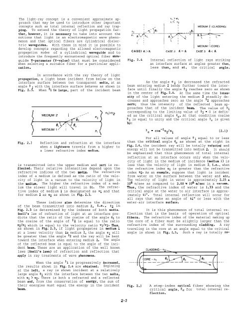
CASEI 01>0, CASE2 e)=ec CASE3: 01 n2. There is both a refracted and a reflected<br />
beam and, from the conservation of energy, the sum of<br />
their energies must equal the energy in the incident<br />
beam.<br />
2-2<br />
Fig. 2.5<br />
A step-index optical fiber showing the<br />
critical angle, 6C for total internal reflection.


