

FIBEROPTIC SENSOR TECHNOLOGY HANDBOOK
FIBEROPTIC SENSOR TECHNOLOGY HANDBOOK
FIBEROPTIC SENSOR TECHNOLOGY HANDBOOK

Create successful ePaper yourself
Turn your PDF publications into a flip-book with our unique Google optimized e-Paper software.
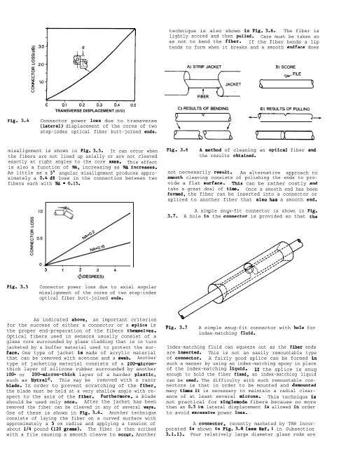
technique is also shown in Fig. 3.6. The fiber is<br />
lightly scored and then pulled. Care must be taken so<br />
as not to bend the fiber. If the fiber bends a lip<br />
tends to form when it breaks and a smooth endface does<br />
A)STRIPJACKET<br />
B)SCORE<br />
~FILE<br />
t<br />
FIBER<br />
6 ?<br />
Fig. 3.4<br />
o 0.1 0.2 0.3 0.4 0:5<br />
TRANSVERSE DISPLACEMENT (d/D)<br />
Connector power loss due to transverse<br />
(lateral) displacement of the cores of two<br />
step-index optical fiber butt-joined enda.<br />
P<br />
C) RESULTS OFFENDING<br />
v<br />
&d<br />
h<br />
D) RESULTS OF PULLING<br />
—~.<br />
misalignment is shown in Fig. 3.5. It can occur when<br />
the fibers are not lined up axially or are not cleaved<br />
exactly at right angles to the core axes. This effect<br />
is also a function of NA, increasing as NA increases.<br />
As little as a 5° angular misalignment produces approximately<br />
a 0.4 dB loss in the connection between two<br />
fibers each with NA = 0.15.<br />
Fig. 3.6<br />
A method of cleaning an optical fiber and<br />
the results obtained.<br />
not necessarily result. An alternative approach to<br />
amooth cleaving consists of polishing the ends to provide<br />
a flat surface. This can be rather costly and”<br />
take a great deal of time. Once a smooth end has been<br />
formed, the fiber can be inserted into a connector or<br />
spliced to another fiber that alao haa a smooth end.<br />
A simple snug-fit connector is shown in Flz.<br />
3.7. A hole in- the c&nector is provided so that tie<br />
o 1“ 4<br />
~(DEGR&<br />
Fig. 3.5<br />
Connector power loss due to axial angular<br />
misalignment of the cores of two step-index<br />
optical fiber butt-joined ends.<br />
As indicated above, an important criterion<br />
for the success of either a connector or a splice is<br />
the proper end-preparation of the fibers themselves.<br />
Optical fibers used in sensors usually consist of a<br />
glass core surrounded by glass cladding that is in turn<br />
jacketed by a buffer material used to protect the surface.<br />
One type of jacket is made of acrylic material<br />
that can be removed with acetone and a swab. Another<br />
type of jacketing material consists of a IOO-micronthick<br />
layer of silicone rubber surrounded by another<br />
100- or 200-micron-thick layer of a harder plastic,<br />
such as Hytrelc. This may be removed with a razor<br />
blade. In order to prevent scratching of the fiber,<br />
the blade must be held at a very shallow angle with respect<br />
to the axis of the fiber. Furthermore, a blade<br />
should be used only once. After the jacket has been<br />
removed the fiber can be cleaved in any of several ways.<br />
One of these is shown in Fig. 3.6. Another technique<br />
consists of laying the fiber on a curved surface with<br />
approximately a 5 cm radius and applying a tension of<br />
about 1/4 pound (120 grams). The fiber is then scribed<br />
with a file causing a smooth cleave to occur. Another<br />
Fig. 3.7 A simple snug-fit connector with hole for<br />
index-matching fluid.<br />
index-matching fluid can squeeze out as the fiber ends<br />
are inserted. This is not an easily remountable type<br />
of connector. A fairly good splice can be formed in<br />
such a manner by using an index-matching epoxy in place<br />
of the index-matching liquid. If the splice is snug<br />
enough to hold the fiber fixed, an index-matching liquid<br />
can be used. The difficulty with such remountable connectors<br />
is that in order to be mounted and demounted<br />
many times it is necessary to maintain a radial clearance<br />
of at least several microns. This technique is<br />
not practical for singlemode fibers because no more<br />
than an 0.5 urn lateral displacement is allowed In order<br />
to avoid excesaive power losa.<br />
A connector, recently marketed by TRW Incorporated<br />
is shown in Fig. 3.8 (see Ref. 1 in Subsection<br />
3.1.1). Four relatively large diameter glass rods are


