

FIBEROPTIC SENSOR TECHNOLOGY HANDBOOK
FIBEROPTIC SENSOR TECHNOLOGY HANDBOOK
FIBEROPTIC SENSOR TECHNOLOGY HANDBOOK

Create successful ePaper yourself
Turn your PDF publications into a flip-book with our unique Google optimized e-Paper software.
CHAPTER 4<br />
LIGHTWAVES IN <strong>FIBEROPTIC</strong> <strong>SENSOR</strong>S<br />
4.1 INTERFEROMRTRIC <strong>FIBEROPTIC</strong><br />
4.1.1 Intensity Interferometry<br />
4.1.1.1 Basic Principles<br />
<strong>SENSOR</strong>S<br />
The basic transduction mechanism employed in<br />
many fiberoptic sensors now being developed is the phase<br />
modulation of coherent light propagating through a section<br />
of singlemode fiber by the action of the energy<br />
field that is to be detected. The techniques of optical<br />
interferometry may be used to detect these phase<br />
shifts in lightwaves. These techniques allow for the<br />
extremely high sensitivity that is achievable with the<br />
various types of interferometric fiberoptic sensors.<br />
Until recently, optical interferometry has been a research<br />
tool used in laboratories rather than an applied<br />
or operational technique. With the development of low-<br />
10SS singlemode optical fibers, subminiature aolidstate<br />
laser light sources, photodetectors, and other<br />
related purely optical and electrooptical devices,<br />
it is now possible to construct practical interferometric-type<br />
devices for use in operational systems. Fiberoptic<br />
sensors have the potential to revolutionize sensor<br />
technology.<br />
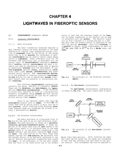
mirror is less than the coherence length of the laser,<br />
the two beams transmitted to the detector can be made<br />
to interfere with one another. The detector output<br />
will go from a maximum to a minimum and back to a maximum<br />
each time the movable mirror is displaced by one<br />
half the optical wavelength. With this technique, it<br />
is ossible to detect mirror displacements as small as<br />
10- ? urn, e.g. 0.63 x 10⁻¹³ m, for a He-Ne laser red<br />
light.<br />
LASER<br />
SPLITTER<br />
TRANSDUCER<br />
Four different interferometric configurations<br />
currently are being employed in fiberoptic aensors.<br />
These are the Michelson, the Mach-Zehnder, the Sagnac,<br />
and the Fabry-Perot configurations. It is convenient<br />
to review their operation in terms of a nonconventional<br />
schematic arrangement using airpaths and bulk optical<br />
components before considering how they may be constructed<br />
with optical fiber elements.<br />
There is one important aspect that these interferometric<br />
sensors have in common. In each one, the<br />
output beam from an optical source is split into two or<br />
more portions. After traveling along different paths,<br />
these separate beams are recombined and allowed to actuate<br />
a photosensitive detector.<br />
4.1.1.2 The Michelson Interferometer<br />
The basic principle is illustrated first in<br />
Fig. 4.1 for the case of an air path Michelson interferometer.<br />
The beam splitter is shown as a partiallyreflective,<br />
partially-transmissive mirror. It sends one<br />
portion of the output beam from the laser upward to the<br />
fixed mirror where it is reflected back to the beam<br />
splitter, where it is then partially transmitted to the<br />
optical detector and partially reflected back toward<br />
the laaer. The other portion of the laser output beam<br />
passes through the beam aplitter, 1S reflected from<br />
the movable mirror to be partially reflected to the<br />
optical detector and partially transmitted back toward<br />
the laser. If the difference in the the path lengths<br />
back and forth to the fixed mirror and to the movable<br />
4-1<br />
4.1.1.3 The Mach-Zehnder Interferometer<br />
The Mach-Zehnder interferometer configuration<br />
is shown in Fig. 4.2. The laser output beam is split<br />
Fig. 4.2<br />
BEAM<br />
w<br />
Fig. 4.1 The principle of the Michelson interferometer.<br />
“’’R’-<br />
1<br />
BEAM<br />
SPLITTER<br />
LASER<br />
I “ ‘<br />
1 , ,<br />
MOVABLE<br />
The principle of the Mack-Zehnder interferometer.<br />
by the lower beam splitter. After traveling the upper<br />
and lower optical paths the two beams are recombined<br />
so that they may interfere with each other at the optical<br />
detector. This arrangement may also be employed to


