

FIBEROPTIC SENSOR TECHNOLOGY HANDBOOK
FIBEROPTIC SENSOR TECHNOLOGY HANDBOOK
FIBEROPTIC SENSOR TECHNOLOGY HANDBOOK

You also want an ePaper? Increase the reach of your titles
YUMPU automatically turns print PDFs into web optimized ePapers that Google loves.
CHAPTER 3<br />
<strong>FIBEROPTIC</strong> COMPONENT INTERCONNECTION<br />
Optical power loss (attenuation) has been<br />
drastically reduced in optical fibers since 1970. A<br />
power loss of 0.2 dB per kilometer has been achieved<br />
and the prospect is good for another order of magnitude<br />
improvement to 0.02 dB per kilometer. If this occurs,<br />
approximately 50 kilometers of fiber would exhibit only<br />
a 1 dB leas. One consequenceof this progress inreducing<br />
attenuation in fiber is the increased importance of<br />
the attenuation associated with component-to-fiber,<br />
fiber-to-fiber, and fiber-to-component interconnections.<br />
Little is accomplished if 0.02 dB per kilometer<br />
attenuation is achieved in optical fibers and at the<br />
same time a number of Interconnections are required,<br />
each resulting in an appreciable fraction of a dB loss.<br />
In the case of fiberoptic sensora, where much shorter<br />
lengths of optical fiber are utilized than in communication<br />
systems, such as several hundred meters of fiber<br />
or less per sensor, and where the fiber used in most<br />
cases is not chosen for low 10SS, problems with interconnections<br />
may be less important although connection<br />
insertion losses can still be a large portion of the<br />
total loss in a fiberoptic sensor. Interconnections,<br />
especially singlemode fiber interconnections, are still<br />
required and therefore of importance. The current<br />
state of their development and manufacture will be considered<br />
in the following discussions.<br />
3.1 ‘<strong>FIBEROPTIC</strong> CONNECTORS AND SPLICES<br />
Some of the uses of interconnections in the<br />
fabrication of fiberoptic sensors include joining<br />
sources and detectors to fiber , splitting the output of<br />
a source (especially laser diodes) among a number of<br />
sensors, beam splitting and combining of light in interferometers,<br />
and providing fiber-to-fiber interconnections.<br />
All interconnections must be designed taking<br />
reflection and consequent insertion losses into account,<br />
with the aim of minimizing the insertion losses.<br />
into which light is being introduced will be designated<br />
the “sink” fiber.<br />
In connectors and splices, power losses fall<br />
into two general classes: intrinsic and extrinsic.<br />
Intrinsic losses are due to variations or imperfections<br />
in the fiber that occur during the manufacturing process<br />
and are not mechanically or externally correctable.<br />
Extrinsic losses are those that occur after the manufacturing<br />
process and are mechanically or externally<br />
correctable, such as incorrect finishing of the fiber<br />
end-surfaces or incorrect mechanical mating of fibers.<br />
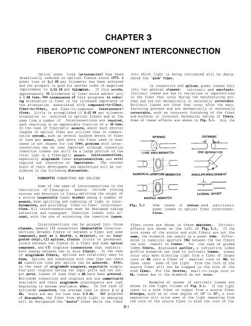
Some of these effects are shown in Fig. 3.1. Only the<br />
x<br />
INTRINSIC<br />
(I:C<br />
CORE AREA MISMATCH<br />
NUMERICAL APERTURE MISMATCH<br />
PROFILE MISMATCH<br />
EXTRINSIC<br />
~ ~d<br />
-c<br />
END SEPARATION<br />
+ p’-<br />
ANGULAR MISALIGNMENT<br />
-L /<br />
t<br />
LATERAL OFFSET<br />
Fig. 3.1 Some causes of intrinsic and extrinsic<br />
power losses in optical fiber interconnections.<br />
Interconnections can be grouped into three<br />
classes, namely (1) connectors (remountable interconnections<br />
between fibers or between a fiber and some<br />
component, such’as a source, a detector, or an integrated<br />
chip), (2) splices, (fusion joints or permanent<br />
joints between two fibers or a fiber and some optical<br />
component, and (3) couplers (connections that redistribute<br />
energy between two or more fibers). In the case<br />
of singlemode fibers, splices are relatively easy to<br />
form. Splices and connectors with less than one tenth<br />
dB insertion loss per splice can be achieved. Also,<br />
in the case of singlemode couplers, especially simple<br />
four-port couplers having two input ports and two output<br />
ports, losses of less than a dB have been achieved.<br />
Multimode connectors and couplers are now commerically<br />
available and their singlemode counterparts are just<br />
beginning to become available also. In the case of<br />
multimode connectors, the average loss is about 1 or 2<br />
dB. Goals are set for less than 0.5 dB. For purposes<br />
of discussion, the fiber from which light is emerging<br />
will be designated the ‘source” fiber while the fiber<br />
3-1<br />
fiber cores are shown in these sketches. Intrinsic<br />
effects are shown on the left of Fig. 3.1. If the<br />
core areas of the source and sink fibers are not the<br />
same, the mismatch can result in a power loss. Differences<br />
in numerical aperture (NA) between the two fibers<br />
can also result in losses. For the case of graded<br />
index fibers, discussed earlier, a refractive index<br />
profile mismatch can lead to intrinsic losses. Losses<br />
occur only when directing light from a fiber of larger<br />
core or NA into a fiber of smaller core or NA. In<br />
these cases some of the light from the core of the<br />
source fiber will not be trapped in the core of the<br />
sink fiber. For the reverse, small-to-large core or<br />
NA, losses due to the mismatch do not occur.<br />
Examples of causes of extrinsic losses are<br />
shown in the right column of Fig. 3.1. If the light<br />
input to a sink fiber or output from a source fiber<br />
diverges, such as at cone angles of 15° to 20”, a core<br />
separation will allow some of the light emanating from<br />
the core of the source fiber to miss the core of the


