

FIBEROPTIC SENSOR TECHNOLOGY HANDBOOK
FIBEROPTIC SENSOR TECHNOLOGY HANDBOOK
FIBEROPTIC SENSOR TECHNOLOGY HANDBOOK

You also want an ePaper? Increase the reach of your titles
YUMPU automatically turns print PDFs into web optimized ePapers that Google loves.
ient configuration in the lower right is produced by<br />
utilizing both arms of the interferometer aa spatially<br />
separated sensors.<br />
5.1.2 Fiberoptic Acoustic Sensors<br />
5.1.2.1 Acoustic Pressure Sensors<br />
Extending the discussion for an acoustic sensor<br />
in Subsection 4.2.1 and considering Eqa. (4.7) and<br />
(4.8), the pressure variations associated with a sound<br />
wave produce phase fluctuations given by:<br />
A$ = kA(nL) = k(nAL + LAn) (5.1)<br />
is more nearly valid. Thus, the phase of a lightwave<br />
in Hytrelc-jacketed optical fiber, where the croas sectional<br />
area of the Hytrelc is much greater than that<br />
of the fused silica, responds to pressure according to<br />
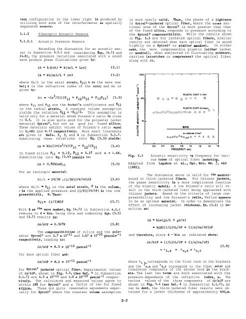
the Hytrelc compressibility. While the results shown<br />
in Fig. 5.3 are for jacketed optical fibers, similar<br />
results are obtained when bare optical fiber is wound<br />
tightly on a Hytrelc or similar mandrel. In either<br />
case, the more compressible plastic (either jacket<br />
or mandrel), when subjected to fluctuating pressure,<br />
carries (atretches or compresses) the optical fiber<br />
along with it.<br />
A$ = kL(nAL/L + An) (5.2)<br />
where AL/L is the axial strain, S11; k is the wave num -<br />
ber; n is the refractive index of the core; and An is<br />
given by:<br />
An = -(n3/2)[(Pll + P12)S12 + P12S11] (5.3)<br />
where Pll and P12 are the Pockel’s coefficients and S12<br />
is the radial strain. A constant volume assumption<br />
yields the relation S12 = -S11/2. This assumption is<br />
valid only for a material whose Poisson’s ratio is close<br />
to 0.5. It is also quite good for the polyester jacket<br />
material Hytrelc, but not as good for fused silica.<br />
These materials exhibit values of Poisson’s ratio equal<br />
to 0.483 and 0.17 respectively. More exact treatments<br />
sre given in Refs. 2, 3, and 4 in Subsection 5.1.7.<br />
Substituting these relations into Eq. (5.3) yields:<br />
A$ = kLn[l+(n2/4)(Pll - p12)]Sll (5.4)<br />
In fused silica Pll = 0.12, P12 = 0.27 and n = 1.46.<br />
Substituting into Eq. (5.4) results in:<br />
A$ = 0.92kLnSll (5.5)<br />
For an isotropic material:<br />
AL/L = Av/3v :(1/3V)(~V/aP)AP (5.6)<br />
where AL/L = S11 is the axial strain, V iS the volume,<br />
P is the applied pressure and (1/V)(aV/ap) iS the com -<br />
pressibility, K. Thus:<br />
S1l = (1/3)KAP (5.7)<br />
With Kaa the wave number, Eq. (4.7) in Subjection 4.2.1<br />
reduces to $ = kLn. Using this and combining Eqs. (5.5)<br />
and (5.7) results in:<br />
A@/@AP = 0.307K (5.8)<br />
The compressibilities of silica and the pol~~<br />
ester Hytrelc are 2.7 x 10⁻¹¹ and 2.67 x 10⁻¹⁰ pascals<br />
respectively, leading to:<br />
A$/$AP = 8.3 x 10⁻¹² pascal-l<br />
for bare optical fiber and:<br />
A$/$AP = 8.2 x 10⁻¹¹ pascal-l<br />
for Hytrelc jacketed optical fiber. Experimental values<br />
of A$/$AP, shown in Fig. 5.3, (See Ref. 5 in Subsection<br />
5.1.7) are 4.5 x 10⁻¹² and 1.0 x 10⁻¹⁰ pascal-l respectively.<br />
The calculated and measured values agree to<br />
within 18% for Hytrelc and a factor of two for fused<br />
silica. These are quite reasonable agreements especially<br />
for Hytrelc where the constant volume assumption<br />
~lo -<br />
In<br />
PIJSTICCOAT(lmm)<br />
❑ DD<br />
❑ ODDDU ❑<br />
PLASTIC COAT (O.4 mm)<br />
00<br />
Ooooo(looooooooo(x o 0 0<br />
Q$<br />
SARE<br />
$<br />
<<br />
ALUMINUM COAT<br />
AAAAAAAAAAA A A 6 A A<br />
1 1 , 1 1 1 1<br />
0.2 0.4 O.b 0.8 10 12 1.4 16<br />
FREQUENCY (kHz)<br />
Fig. 5.3 Acoustic sensitivity vs frequency for various<br />
typea of optical fiber jacketing.<br />
Adapted from Lagakos et al., Opt. Soc. Am. ~, 460<br />
(1982).<br />
The discussion above is valid for the mandrelwound<br />
or thick-jacketed fibers. For thinner jackets,<br />
the phase sensitivity is a more complicated function<br />
of the elastic moduli. A low Poisson’s ratio will result<br />
in the thick-jacketed limit being approached with<br />
thinner jackets. Baaed on the criteria of large compressibility<br />
and low Poisson’s ratio, Teflon c appeara<br />
to be an optimum material. In order to demonstrate the<br />
effect of increasing jacket thickness. Ea. (5.2) is rewritten<br />
as:<br />
A$ = kLn(AL/L + An/n)<br />
= kLN[(l/L)aL/aP +<br />
and therefore, since $ = kLn as<br />
A$/$AP = (1/L)aL/aP +<br />
(1/n)an/aP]AP<br />
indicated above:<br />
(1/n)an/aP)<br />
‘CL,Z + Cn,z+cn,r<br />
J<br />
1<br />
(5.9)<br />
where CL z corresponds to the first term in the brackets<br />
and the 2n,z and cn,r correspond to the fiber axial and<br />
transverse components of the second term in the brackets.<br />
The last two terma are both associated with the<br />
pressure-dependence of the refractive index, n. The<br />
various values of the three components of A$/$AP are<br />
shown in Fig. 5.4 (see Ref. 4 in Subsection 5.1.7). As<br />
can be seen, the thick-jacketed fiber results were obtained<br />
for a jacket thickness of approximately 600Pm.<br />
5-2


