

FIBEROPTIC SENSOR TECHNOLOGY HANDBOOK
FIBEROPTIC SENSOR TECHNOLOGY HANDBOOK
FIBEROPTIC SENSOR TECHNOLOGY HANDBOOK

Create successful ePaper yourself
Turn your PDF publications into a flip-book with our unique Google optimized e-Paper software.
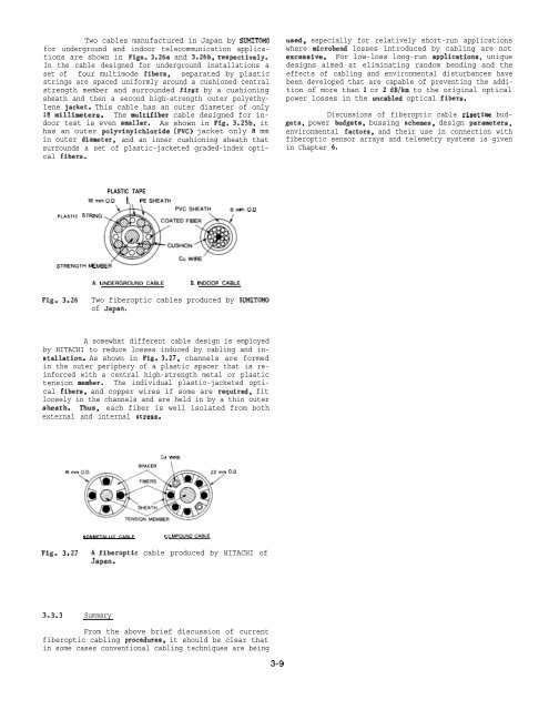
Two cables manufactured in Japan by SUMITOMO<br />
for underground and indoor telecommunication applications<br />
are shown in Figs. 3.26a and 3.26b, respectively.<br />
In the cable designed for underground installations a<br />
set of four multimode fibers, separated by plastic<br />
strings are spaced uniformly around a cushioned central<br />
strength member and surrounded first by a cushioning<br />
sheath and then a second high-strength outer polyethylene<br />
jacket. This cable has an outer diameter of only<br />
18 millimeters. The multifiber cable designed for indoor<br />
test is even smaller. As shown in Fig. 3.25b, it<br />
has an outer polyvinylchloride (PVC) jacket only 8 mm<br />
in outer diameter, and an inner cushioning sheath that<br />
surrounds a set of plastic-jacketed graded-index optical<br />
fibers.<br />
used, especially for relatively short-run applications<br />
where microbend losses introduced by cabling are not<br />
excessive. For low-loss long-run applications, unique<br />
designs aimed at eliminating random bending and the<br />
effects of cabling and environmental disturbances have<br />
been developed that are capable of preventing the addition<br />
of more than 1 or 2 dB/km to the original optical<br />
power losses in the uncabled optical fibers.<br />
Discussions of fiberoptic cable risetime budgets,<br />
power budgets, bussing schemes, design parameters,<br />
environmental factors, and their use in connection with<br />
fiberoptic sensor arrays and telemetry systems is given<br />
in Chapter 6.<br />
PLASTIC STR<br />
PLASTIC TAPE<br />
ISmmOD ~ PESHEATH<br />
mO.D<br />
STRENGTHM<br />
A. underground CABLE B. INDOOR CABLE<br />
Fig. 3.26<br />
Two fiberoptic cables produced by SUMITOMO<br />
of Japan.<br />
A somewhat different cable design is employed<br />
by HITACHI to reduce losses induced by cabling and installation.<br />
As shown in Fig. 3.27, channels are formed<br />
in the outer periphery of a plastic spacer that is reinforced<br />
with a central high-strength metal or plastic<br />
tension member. The individual plastic-jacketed optical<br />
fibers, and copper wires if some are required, fit<br />
loosely in the channels and are held in by a thin outer<br />
sheath. Thus, each fiber is well isolated from both<br />
external and internal stress.<br />
CU WIRE<br />
16mm<br />
SPACER \<br />
O.D<br />
NONMETALLIC CABLE<br />
co MPOUNDCASLE<br />
Fig. 3.27<br />
A fiberoptic cable produced by HITACHI of<br />
Japan.<br />
3.3.3 Summary<br />
From the above brief discussion of current<br />
fiberoptic cabling procedures, it should be clear that<br />
in some cases conventional cabling techniques are being<br />
3-9


