

FIBEROPTIC SENSOR TECHNOLOGY HANDBOOK
FIBEROPTIC SENSOR TECHNOLOGY HANDBOOK
FIBEROPTIC SENSOR TECHNOLOGY HANDBOOK

You also want an ePaper? Increase the reach of your titles
YUMPU automatically turns print PDFs into web optimized ePapers that Google loves.
fibers are cleaned carefully after removing the jacket.<br />
Then they are twisted together and while remaining<br />
twisted they are etched to remove most of the cladding,<br />
leaving approximately one or two microns of cladding<br />
around the core. The diameters of the fibers after<br />
etching are less than 10% of their initial diameters,<br />
therefore the resulting sections of fibers are quite<br />
fragile. The joint IS held fixed (ruggedized) by either<br />
potting in an indexmatching material or by fusing under<br />
an axial tension that prevents the fiber from sagging<br />
due to gravity and at the same time stretches the fiber<br />
slightly, thus forming a biconical taper. This is shown<br />
in Fig. 3.20 on the right. Index matching silicone<br />
liquids have been proven to be highly temperature dependent.<br />
Better results are obtained with index-matching<br />
silicone rubber. However, there is still a temperaturedependence<br />
problem. A great deal of success has been<br />
achieved recently using a gel glass material (see Ref.<br />
2 in Subsection 3.2.1) that is initially in liquid form.<br />
This material consists of metal oxides dissolved in an<br />
organic material. When heated the organic material is<br />
driven off and the metal oxides form a glass. The refractive<br />
index of the resulting glasa, and therefore<br />
the degree of coupling, can be controlled by adjusting<br />
the temperature and the length of time utilized to cure<br />
or form the gel glass.<br />
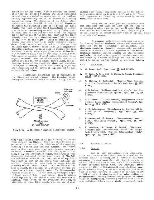
Temperature dependence can be minimized if<br />
the fibers are actually fused. The biconical taper<br />
arrangement mentioned above is shown in Fig. 3.21. To<br />
aturized bulk optical components similar to the laboratory<br />
devices shown in Figs 3.16, 3.17, and 3.18. These<br />
bulk components and fibers may be connected by various<br />
means, such as GRIN rods.<br />
Using similar techniques star couplers have<br />
been fabricated that allow the light from one fiber to<br />
be coupled equally into as many as 32 other fibers.<br />
Such devices would be useful for permitting a single<br />
optical source to simultaneously furnish optical power<br />
to a number of sensors.<br />
In summary, satisfactory techniques now exist<br />
for forming low-loss singlemode splices and remountable<br />
connectors and for fabricating low insertion loss<br />
singlemode couplers. Recently, commercially available<br />
remountable connectors have appeared on the market.<br />
Singlemode biconical tapered couplera are also becoming<br />
available. Several other types of couplers are under<br />
development by a number of groups and thus can be expected<br />
to appear on the market in the near future.<br />
3.2.1 References<br />
1.<br />
2.<br />
3.<br />
S. Sheem, Appl. Phys. Lett ~, 869 (1980).<br />
D. Tran, K. Koo, and S. Sheem, J. Quant. Electron.<br />
QE-17, 988 (1981).<br />
R. Ulrich, S. Rashleigh, ‘Beam-to-Fiber Coupling<br />
with Low Standing-Wave Rtutio”, Appl. Opt. ~, 2453<br />
(1980).<br />
END VIEW<br />
OF FIBER<br />
4.<br />
G.B. Hocker, “Unidirectional Star Coupler for Single-Fiber<br />
Distribution System”, Opt. Lett. ~, 124<br />
(1977).<br />
5.<br />
S. K. Sheem, T. G. Giallorenzi, “Single-Mode Fiber<br />
Optical Power Divider: Encapsulated Etching”, Opt.<br />
Lett. ~, 29 (1979).<br />
6.<br />
J. G. Ackerhusen, “Microlenses to Improve LED-to-<br />
Fiber Optical Coupling”, Appl. Opt. ~, 3694<br />
(1979).<br />
Fig. 3.21<br />
CROSS SECTION<br />
VIEW<br />
OF FUSED COUPLER<br />
A biconical (tapered)<br />
fiberoptic coupler.<br />
7.<br />
8.<br />
M. Saruwatari, K. Nawata, “Semiconductor Laaer to<br />
Single-Mode Fiber Coupler”, APP1. Opt. ~, 1847<br />
(1979).<br />
H. Kuwahara, N. Tokoyo, M. Sasaki, “Efficient<br />
Coupling from Semiconductor Lasers into Single-<br />
Mode Fibers with Tapered Heimspherical Ends”,<br />
Appl. Opt. g, 2578 (1980).<br />
make this coupler a portion of the cladding is removed<br />
from each of ‘the fibers. These are then twisted together<br />
and etched until the thickness of the remaining<br />
cladding is about half the core diameter. The twisted<br />
pair is then fused under some axial tension causing a<br />
decrease in diameter, especially in the region of contact,<br />
i.e., the interaction region. The original core<br />
dimensions indicated in the upper right of Fig. 3.21<br />
are reduced as shown in the lower center of Fig. 3.21.<br />
The result is that optical energy that initially was<br />
confined close to the core tends to spread into the<br />
cladding in the region where the core diameter has<br />
been decreased. This results in a stronger overlap and<br />
therefore a higher coupling ratio. The Electrooptics<br />
Product Division of ITT has recently developed a specialized<br />
optical fiber that allows them to produce<br />
fused copulers by this method without the necesaity of<br />
etching. These couplers are available for sale. An<br />
alternate to these fiber couplers is the use of mini-<br />
3.3 <strong>FIBEROPTIC</strong> CABLES<br />
3.3.1 General<br />
Just as with conventional wire interconnections<br />
and communication links, there is a need for fiberoptic<br />
cables to accomplish a number of different<br />
purposea. In many ways, the individual fibers in an<br />
optical cable are treated very much like varnished or<br />
plastic insulated copper wires. The individual fibera<br />
consist of 100- to 200-micron-OD core-cladding waveguide<br />
elements having an outer coating that may be as<br />
thin as several microns of lacquer or as thick as 200<br />
to 400 microns of plastic, such as nylon, teflon, or<br />
polypropylene. Cabling serves the purpose of spacedivision<br />
multiplexing, combining anywhere from a few to<br />
many individual fibers into a single conveniently-pack-<br />
3-7


