

FIBEROPTIC SENSOR TECHNOLOGY HANDBOOK
FIBEROPTIC SENSOR TECHNOLOGY HANDBOOK
FIBEROPTIC SENSOR TECHNOLOGY HANDBOOK

Create successful ePaper yourself
Turn your PDF publications into a flip-book with our unique Google optimized e-Paper software.
left. The ends of the two fibers are brought together<br />
wittmut necessarily eliminating lateral displacement.<br />
Upon heating, the fiber melts and surface tensions tend<br />
to align the fibers as shown. The graph on the right<br />
side of Fig. 3.12 shows connector loss as a function<br />
of lateral displacement both before and after heating.<br />
The results prior to fusing is a theoretical curve with<br />
experimental reaults superimposed. As can be seen a<br />
significant reduction in loss is realized as a reault<br />
of fusion splicing.<br />
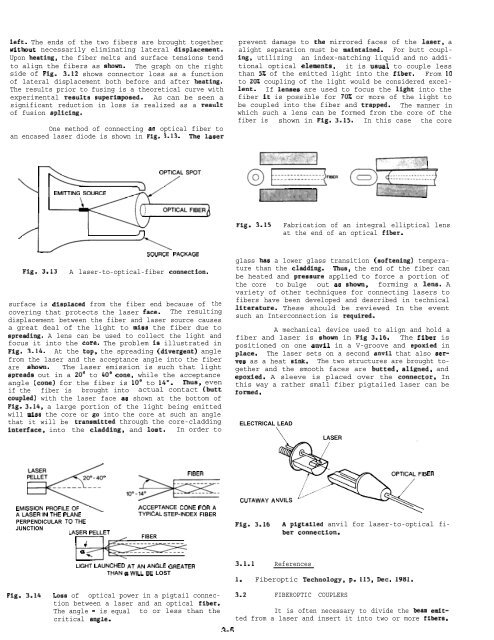
One method of connecting an optical fiber to<br />
an encased laser diode is shown in Fig. 3.13. The laser<br />
prevent damage to the mirrored faces of the laser, a<br />
alight separation must be maintained. For butt coupling,<br />
utilizing an index-matching liquid and no additional<br />
optical elementa, it is us~i to couple less<br />
than 5% of the emitted light into the fiber. From 10<br />
to 20% coupling of the light would be considered excellent.<br />
If lenaes are used to focus the light into the<br />
fiber it is possible for 70% or more of the light to<br />
be coupled into the fiber and trapped. The manner in<br />
which such a lens can be formed from the core of the<br />
fiber is shown in Fig. 3.15. In this case the core<br />
OPTICAL SPOT<br />
EMITTING SOURCE<br />
/ /1 I n<br />
Fig. 3.15<br />
Fabrication of an integral elliptical lens<br />
at the end of an optical fiber.<br />
Fig. 3.13<br />
SOURCE PACKAGE<br />
A laser-to-optical-fiber connection.<br />
surface is displaced from the fiber end because of the<br />
covering that protects the laser face. The resulting<br />
displacement between the fiber and laser source causes<br />
a great deal of the light to miss the fiber due to<br />
spreading. A lens can be used to collect the light and<br />
focus it into the core. The problem is illustrated in<br />
Fig. 3.14. At the top, the spreading (divergent) angle<br />
from the laser and the acceptance angle into the fiber<br />
are ahown. The laser emission is such that light<br />
apreads out in a 20° to 40° cone, while the acceptance<br />
angle (cone) for the fiber is 10° to 14”. Thus, even<br />
if the fiber is brought into actual contact (butt<br />
coupled) with the laser face aa shown at the bottom of<br />
Fig. 3.14, a large portion of the light being emitted<br />
will mlaa the core or go into the core at such an angle<br />
that it will be trans~tted through the core-cladding<br />
interface, into the cladding, and lost. In order to<br />
glass haa a lower glass transition (softening) temperature<br />
than the cladding. Thus, the end of the fiber can<br />
be heated and preasure applied to force a portion of<br />
the core to bulge out aa shown, forming a lens. A<br />
variety of other techniques for connecting lasers to<br />
fibers have been developed and described in technical<br />
literature. These should be reviewed In the event<br />
such an Interconnection is required.<br />
A mechanical device used to align and hold a<br />
fiber and laser is ahown in Fig 3.16. The fiber is<br />
positioned on one anvil in a V-groove and epoxied in<br />
place. The laser sets on a second anvil that also aerves<br />
as a heat aink. The two structures are brought together<br />
and the smooth faces are butted, aligned, and<br />
epoxied. A sleeve is placed over the connector. In<br />
this way a rather small fiber pigtailed laser can be<br />
formed.<br />
ELECTRICAL LEAD<br />
LASER<br />
@ ,oo--<br />
ER<br />
EMISSION PROFILEOF<br />
ALASERIN THE PLANE<br />
PERPENDICULAR TOTHE<br />
JUNCTION<br />
LASER PELLET<br />
+<br />
a.<br />
E:<br />
ACCEPTANCE CONE FORA<br />
TYPICAL STEP-INDEX FIBER<br />
FIBER<br />
LIGHT LAUNCHED ATAN ANGLE GREATER<br />
THANaWILLBE LOST<br />
CUTAWAYA<br />
Fig. 3.16<br />
3.1.1 References<br />
A pigtailed anvil for laser-to-optical<br />
ber connection.<br />
1. Fiberoptic Technology, p. 115, Dec. 1981.<br />
fi-<br />
Fig. 3.14<br />
Loas of optical power in a pigtail connection<br />
between a laser and an optical fiber.<br />
The angle = is equal to or less than the<br />
critical angle.<br />
2-5<br />
3.2 <strong>FIBEROPTIC</strong> COUPLERS<br />
It is often necessary to divide the beam emitted<br />
from a laser and insert it into two or more fibera.


