

FIBEROPTIC SENSOR TECHNOLOGY HANDBOOK
FIBEROPTIC SENSOR TECHNOLOGY HANDBOOK
FIBEROPTIC SENSOR TECHNOLOGY HANDBOOK

Create successful ePaper yourself
Turn your PDF publications into a flip-book with our unique Google optimized e-Paper software.
detect displacements of the movable mirror as small as<br />
10-13 m. l%is configuration has the advantage that<br />
little or no light is fed directly back into the laser.<br />
This is in contrast to the Michelson configuration. A<br />
more detailed description of how such feedback can lead<br />
to laser instability and noise is contained in Section<br />
4.2. It should be noted that there are two other beams<br />
not shown explicitly in Fig. 4.2, that travel upward<br />
from the second beam splitter, i.e. a reflected portion<br />
of the upper horizontal beam and a transmitted portion<br />
of the righthand vertical beam. These could be fed to<br />
another optical detector to yield a second output signal<br />
, which may be employed to advantage in certain applications.<br />
4.1.1.4 The<br />
Sagnac<br />
Interferometer<br />
Fig. 4.4<br />
—<br />
1<br />
FIXED<br />
t<br />
MOVABLE<br />
MIRROR<br />
MIRROR<br />
TRANSDUCER<br />
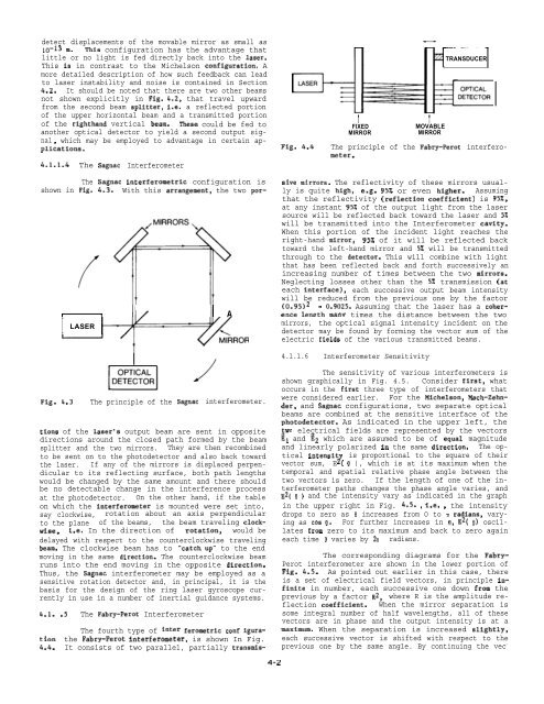
The principle of the Fabry-Perot interferometer.<br />
The<br />
shown in Fig.<br />
Sagnac interferometric configuration is sive mirrors. The reflectivity of these mirrors usually<br />
is quite high, e.g. 95% or even higher. Assuming<br />
4.3. With this arrangement, the two porthat<br />
the reflectivity (reflection coefficient) is 95%,<br />
at any instant 95% of the output light from the laser<br />
source will be reflected back toward the laser and 5%<br />
will be transmitted into the Interferometer cavity.<br />
When this portion of the incident light reaches the<br />
right-hand mirror, 95% of it will be reflected back<br />
toward the left-hand mirror and 5% will be transmitted<br />
through to the detector. This will combine with light<br />
that has been reflected back and forth successively an<br />
increasing number of times between the two mirrors.<br />
Neglecting losses other than the 5% transmission (at<br />
each interface), each successive output beam intensity<br />
will be reduced from the previous one by the factor<br />
II<br />
II<br />
(0.95)2 = 0.9025. Assuming that the laser has a coher-<br />
) 1 11/ I A ence lenzth manv times the distance between the two<br />
mirrors, the optical signal intensity incident on the<br />
LASER<br />
I<br />
Fig. 4.3 The principle of the Sagnac interferometer.<br />
tions of the laser’s output beam are sent in opposite<br />
directions around the closed path formed by the beam<br />
splitter and the two mirrors. They are then recombined<br />
to be sent on to the photodetector and also back toward<br />
the laser. If any of the mirrors is displaced perpendicular<br />
to its reflecting surface, both path lengths<br />
would be changed by the same amount and there should<br />
be no detectable change in the interference process<br />
at the photodetector. On the other hand, if the table<br />
on which the interferometer is mounted were set into,<br />
say clockwise, rotation about an axis perpendicular<br />
to the plane of the beams, the beam traveling clockwiae,<br />
i.e. In the direction of rotation, would be<br />
delayed with respect to the counterclockwise traveling<br />
beam. The clockwise beam has to “catch up” to the end<br />
moving in the same direction. The counterclockwise beam<br />
runs into the end moving in the opposite direction.<br />
Thus, the Sagnac interferometer may be employed as a<br />
sensitive rotation detector and, in principal, it is the<br />
basis for the design of the ring laser gyroscope currently<br />
in use in a number of inertial guidance systems.<br />
4.1.<br />
tion<br />
4.4.<br />
.5 The Fabry-Perot Interferometer<br />
The fourth type of inter ferometric conf igurathe<br />
Fabry-Perot interferometer, is shown In Fig.<br />
It consists of two parallel, partially transmis-<br />
4-2<br />
detector may be found by forming the vector sum of the<br />
electric fields of the various transmitted beams.<br />
4.1.1.6 Interferometer Sensitivity<br />
The sensitivity of various interferometers is<br />
shown graphically in Fig. 4.5. Consider first, what<br />
occurs in the first three type of interferometers that<br />
were considered earlier. For the Michelson, Mach-Zehnder,<br />
and Sagnac configurations, two separate optical<br />
beams are combined at the sensitive interface of the<br />
photodetector. As indicated in the upper left, the<br />
wo electrical fields are represented by the vectors<br />
~1 and 22 which are assumed to be of equal magnitude<br />
and linearly polarized in the same direction. The optical<br />
intensit is proportional to the square of their<br />
vector sum, E z ( 8 ), which is at its maximum when the<br />
temporal and spatial relative phase angle between the<br />
two vectors is zero. If the length of one of the interferometer<br />
paths changes the phase angle varies, and<br />
E2( e ) and the intensity vary as indicated in the graph<br />
in the upper right in Fig. 4.5. , i.e. , the intensity<br />
drops to zero as 13 increases from O to n radians, varying<br />
as cos e. For further increases in e, E2( e) oscillates<br />
from zero to its maximum and back to zero again<br />
each time 13 varies by 2T radians.<br />
The corresponding diagrams for the Fabry-<br />
Perot interferometer are shown in the lower portion of<br />
Fig. 4.5. As pointed out earlier in this case, there<br />
is a set of electrical field vectors, in principle infinite<br />
in number, each successive one down from the<br />
previous by a factor R2, where R is the amplitude reflection<br />
coefficient. When the mirror separation is<br />
some integral number of half wavelengths, all of these<br />
vectors are in phase and the output intensity is at a<br />
maximum. When the separation is increased slightly,<br />
each successive vector is shifted with respect to the<br />
previous one by the same angle. By continuing the vec -


