

FIBEROPTIC SENSOR TECHNOLOGY HANDBOOK
FIBEROPTIC SENSOR TECHNOLOGY HANDBOOK
FIBEROPTIC SENSOR TECHNOLOGY HANDBOOK

You also want an ePaper? Increase the reach of your titles
YUMPU automatically turns print PDFs into web optimized ePapers that Google loves.
in the right center of Fig. 2.13. They increase in<br />
magnitude from zero along the axis of the core to a<br />
maximum and then decay as the core-cladding interface<br />
is approached, as shown in the lower right. As already<br />
pointed out for the HE1l mode in this case, the fields<br />
again extend beyond the core into the cladding.<br />
Returning to the graph at the left in Fig.<br />
2.13, as V is increased further, for example by decreasing<br />
the wavelength, ,10, of the light injected into<br />
the fiber, additional relatively lossless modes are permitted<br />
and, very rapidly, propagation phenomena change<br />
from the single or few mode types to multimode behavior.<br />
In fact, for V > 10 the number of allowed modes is approximately<br />
equal to V2/2 for a step-index fiber. As<br />
already pointed out above in the discussion of the radial<br />
electric field distribution for the HE1l and TEOl<br />
modes, shown in the lower right in Fig. 2.12 and 2.13,<br />
respectively, the ~-fields may extend well beyond the<br />
core cladding interface. In fact when each mode is<br />
first allowed much of its energy is associated with<br />
fields that penetrate the cladding. This phenomena is<br />
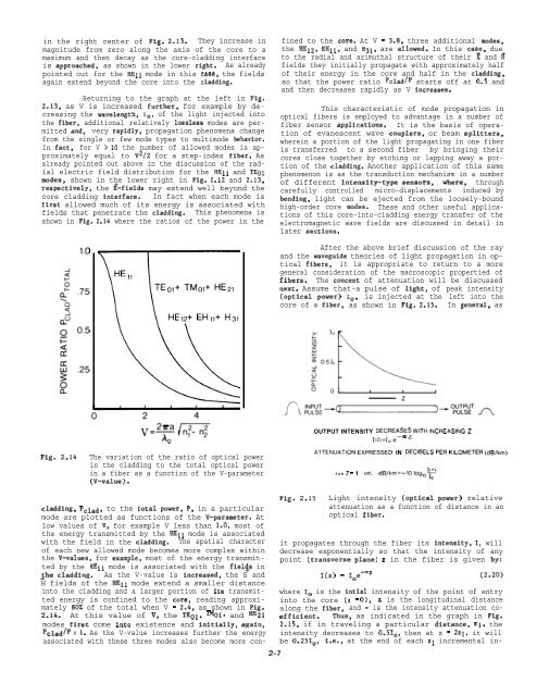
shown in Fig. 2.14 where the ratios of the power in the<br />
cladding, pclad, to the total power, F’, in a particular<br />
mode are plotted as functions of the V-parameter. At<br />
low values of V, for example V less than 1.0, most of<br />
the energy transmitted by the HE1l mode is associated<br />
with the field in the cladding. The spatial character<br />
of each new allowed mode becomes more complex within<br />
the V-values, for example, most of the energy transmitted<br />
by the HE1l mode is associated with the fiel~s in<br />
$he cladding. As the V-value is increased, the E and<br />
H fields of the HE1l mode extend a smaller distance<br />
into the cladding and a larger portion of its transmitted<br />
energy is confined to the core, reading approximately<br />
80% of the total when V = 2.4, as shown in Fig.<br />
2.14. At this value of V, the TEOl, TMOl, and HE21<br />
modes first come into existence and initially, again,<br />
pcladtpz 1. As the V-value increases further the energy<br />
associated with these three modes also become more confined<br />
to the core. At V = 3.8, three additional modes,<br />
the HE12, EH1l, and H31, are allowed. In this case, due<br />
to the radial and azimuthal structure of their ~ and P<br />
fields they initially propagate with approximately half<br />
of their energy in the core and half in the cladding,<br />
so that the power ratio Pclad/P starts off at 0.5 and<br />
and then decreases rapidly as V increases.<br />
This characteristic of mode propagation in<br />
optical fibers is employed to advantage in a number of<br />
fiber sensor applications. It is the basis of operation<br />
of evanescent wave couplers, or beam splitters,<br />
wherein a portion of the light propagating in one fiber<br />
is transferred to a second fiber by bringing their<br />
cores close together by etching or lapping away a portion<br />
of the cladding. Another application of this same<br />
phenomenon is as the transduction mechanism in a number<br />
of different intenaity-type aensors, where, through<br />
carefully controlled micro-displacements induced by<br />
bending, light can be ejected from the loosely-bound<br />
high-order core modes. These and other useful applications<br />
of this core-into-cladding energy transfer of the<br />
electromagnetic wave fields are discussed in detail in<br />
later sections.<br />
After the above brief discussion of the ray<br />
and the waveguide theories of light propagation in optical<br />
fibers, it is appropriate to return to a more<br />
general consideration of the macroscopic propertied of<br />
fibers. The conceut of attenuation will be discussed<br />
next. Assume that-a pulse of light, of peak intensity<br />
(optical power) 1., is injected at the left into the<br />
core of a fiber, as shown in Fig. 2.15. In general, as<br />
OUTPUT INTENSITY DECREASES WI’H INCREASING<br />
IIZ)=Ioe–az<br />
Fig. 2.14 The variation of the ratio of optical power<br />
in the cladding to the total optical power<br />
in a fiber as a function of the V-parameter<br />
(V-value).<br />
ATTENUATION EXPRESSED IN DECIBELS PER KILOMETER (dB/km)<br />
I(z)<br />
FOR Z . 1 km, dB/km=–lOloglo~<br />
2-7<br />
Fig. 2.15 Light intensity (optical power) relative<br />
attenuation as a function of distance in an<br />
optical fiber.<br />
it propagates through the fiber its intensity, I, will<br />
decrease exponentially so that the intensity of any<br />
point (transverse plane) z in the fiber is given by:<br />
I(z) = Ioe-az (2.20)<br />
where 10 is the intial intensity of the point of entry<br />
into the core (z = O), z is the longitudinal distance<br />
along the fiber, and = is the intensity attenuation coefficient.<br />
Thus, as indicated in the graph in Fig.<br />
2.15, if in traveling a particular distance, z1, the<br />
intensity decreases to 0.51., then at z = 2z1, it will<br />
be 0.251., i.e., at the end of each Z1 incremental in-


