

FIBEROPTIC SENSOR TECHNOLOGY HANDBOOK
FIBEROPTIC SENSOR TECHNOLOGY HANDBOOK
FIBEROPTIC SENSOR TECHNOLOGY HANDBOOK

You also want an ePaper? Increase the reach of your titles
YUMPU automatically turns print PDFs into web optimized ePapers that Google loves.
tor addition indefinitely, as indicated in the lower<br />
left, one can easily show that E2(13) in this case is a<br />
sharply peaked function with maxims at = O, Zm, 411,...<br />
and s. forth; E2(e) rapidly decreases and remains CIOSe<br />
to zero for values of f3 only slightly different from O,<br />
2n, 41r,... etc., as indicated in the vector diagram at<br />
the lower center in Fig. 4.5c. Thus, in the vicinity<br />
of its maxima, the Fabry-Perot interferometer is an extremely<br />
sensitive position and length measuring device.<br />
It is in fact, one of the most sensitive displacement<br />
measuring devices available to modern science.<br />
that are currently available, it is already possible to<br />
construct relatively small-sized, highly-stable, and<br />
quite rugged interferometric fiberoptic sensors that<br />
are capable of withstanding the rigors of many fieldtype<br />
applications.<br />
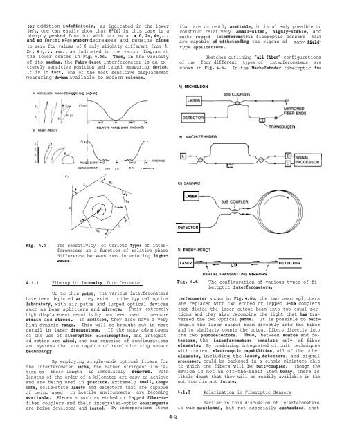
Sketches outlining “all fiber” configurations<br />
of the four different types of interferometers are<br />
shown in Fig. 4.6. In the Mach-Zehnder fiberoptic in-<br />
A) MICHELSON<br />
A) MICHELSON, MACH-ZEHNDER AND SAGNAC<br />
3dB COUPLER<br />
B) FA6Ry-pEROT<br />
El > ~<br />
A<br />
RELATIVE PHASE SHIFT (RADIANS)<br />
=;:’’:;s<br />
RTRANSDUCER<br />
B) MACH-ZEHNDER<br />
E’[@),<br />
r<br />
5’=i!4._-!=-!’=f<br />
\<br />
DISPLACEMENT- O.25 05 0.75 I MICRON<br />
C) SAGNAC<br />
LASER<br />
El<br />
DETECTOR<br />
Fig. 4.5<br />
4.1.2<br />
The sensitivity of various typea of interferometers<br />
as a function of relative phase<br />
difference between two interfering lightwavea.<br />
Fiberoptic Intenaity<br />
Interferometer<br />
Up to this point, the various interferometers<br />
have been depicted aa they exist in the typical optics<br />
laboratory, with air paths and lumped optical devices<br />
such as beam splitters and mirrora. Their extremely<br />
high displacement sensitivity has been used to measure<br />
atrain and streas. In addition, they also have a very<br />
high dynamic range. This will be brought out in more<br />
detail in later discussion. If the many advantages<br />
of the use of fiberoptic, electrooptics, and integrat -<br />
ed-optics are added, one can conceive of configurations<br />
and systems that are capable of revolutionizing sensor<br />
technology.<br />
By employing single-mode optical fibers for<br />
the interferometer paths, the rather stringent limitation<br />
on their length is immediately removed. Path<br />
lengths of the order of a kilometer are easy to achieve<br />
and are being used in practice. Extremely small, longlife,<br />
solid-state laaers and detectors that are capable<br />
of being used in hostile environments are becoming<br />
available. Elements such as etched or lapped fiber-tofiber<br />
couplers and their integrated-optic counterpart<br />
are being developed and tested. By incorporating items<br />
D) FABRY-PEROT<br />
LASER - 1 !- DETECTOR<br />
a<br />
\: ‘/<br />
PARTIAL TRANSMITTING MIRRORS<br />
Fig. 4.6<br />
The configuration of various types of fiberoptic<br />
interferometera.<br />
terferometer shown in Fig. 4.6b, the two beam splitters<br />
are replaced with two etched or lapped 3-db couplers<br />
that divide the laser output beam into two equal portions<br />
and they also recombine the light that haa traversed<br />
the two optical paths. It is possible to buttcouple<br />
the laser output beam directly into the fiber<br />
and to similarly couple the output fibers directly into<br />
the two photodetectors. Thus, between aource and detectors,<br />
the interferometera consiats only of fiber<br />
elementa. By combining integrated circuit techniques<br />
with current electrooptic capabilities, all of the other<br />
elements, including the laser, detectors, and signal<br />
processor, could be packaged in a single miniature chip<br />
to which the fibers will be butt-coupled. Though the<br />
device is not an off-the-shelf item today, there is<br />
little doubt that they will be readily available in the<br />
not too distant future.<br />
4-3<br />
4.1.3 Polarization in Fiberoptic Sensors<br />
Earlier in this discussion of interferometers<br />
it was mentioned, but not especially emphasized, that


