

FIBEROPTIC SENSOR TECHNOLOGY HANDBOOK
FIBEROPTIC SENSOR TECHNOLOGY HANDBOOK
FIBEROPTIC SENSOR TECHNOLOGY HANDBOOK

You also want an ePaper? Increase the reach of your titles
YUMPU automatically turns print PDFs into web optimized ePapers that Google loves.
1<br />
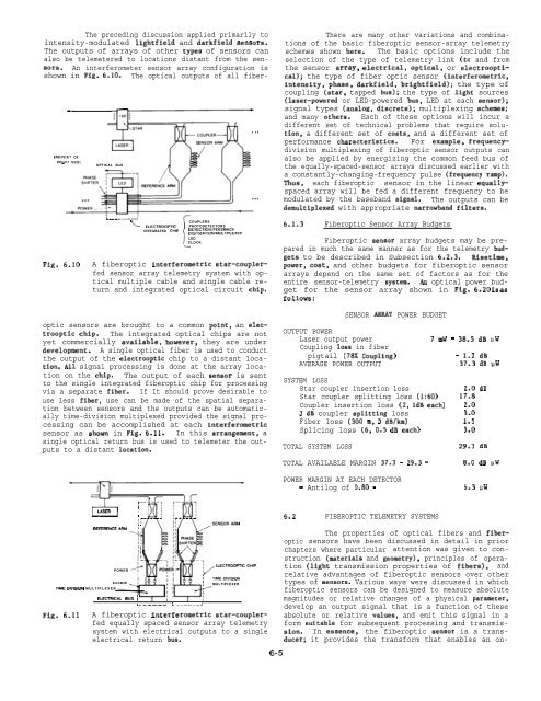
The preceding discussion applied primarily to<br />
intensity-modulated lightfield and darkfield sensors.<br />
The outputs of arrays of other tYPes of sensors can<br />
also be telemetered to locations distant from the sensors.<br />
An interferometer sensor array configuration is<br />
shown in Fig. 6.10. The optical outputs of all fiber-<br />
(REPEAT OF<br />
R,G”T S,DE,<br />
Fig. 6.10<br />
OPTICAL BuS<br />
mL——...-.!<br />
\<br />
I<br />
COUPLERS<br />
ELECTROOPTIC PHOTODETECTORS<br />
INTEGRATED CHIP DETECTIONIFEEDBACK<br />
DIGITIZATION(MULTIPLEXER<br />
LED<br />
CLOCK<br />
L<br />
A fiberoptic interferometric star-couplerfed<br />
sensor array telemetry system with optical<br />
multiple cable and single cable return<br />
and integrated optical circuit chip.<br />
. . .<br />
There are many other variations and combinations<br />
of the basic fiberoptic sensor-array telemetry<br />
schemes shown here. The basic options include the<br />
selection of the type of telemetry link (to and from<br />
the sensor array, electrical, optical, or electrooptical);<br />
the type of fiber optic sensor (interferometric,<br />
intensity, phase, darkfield, brightfield); the type of<br />
coupling (star, tapped bus); the type of light sources<br />
(laser-powered or LED-powered bus, LED at each sensor);<br />
signal types (analog, discrete); multiplexing schemes;<br />
and many others. Each of these options will incur a<br />
different set of technical problems that require solution,<br />
a different set of costs, and a different set of<br />
performance characteristics. For example, frequencydivision<br />
multiplexing of fiberoptic sensor outputs can<br />
also be applied by energizing the common feed bus of<br />
the equally-spaced-sensor arrays discussed earlier with<br />
a constantly-changing-frequency pulse (frequency ramp).<br />
Thus, each fiberoptic sensor in the linear equallyspaced<br />
array will be fed a different frequency to be<br />
modulated by the baseband signal. The outputs can be<br />
demultiplexed with appropriate narrowband filters.<br />
6.1.3 Fiberoptic Sensor Array Budgets<br />
Fiberoptic aensor array budgets may be prepared<br />
in much the same manner as for the telemetry budgeta<br />
to be described in Subsection 6.2.3. Risetime,<br />
power, cost, and other budgets for fiberoptic sensor<br />
arrays depend on the same set of factors as for the<br />
entire sensor-telemetry system. tin optical power budget<br />
for the sensor array shown in Fig. 6.20 is as<br />
follows:<br />
optic sensors are brought to a common point, an electrooptic<br />
chip. The integrated optical chips are not<br />
yet commercially available, however, they are under<br />
development. A single optical fiber is used to conduct<br />
the output of the electrooptic chip to a distant location.<br />
Ml signal processing is done at the array location<br />
on the chip. The output of each senaor is sent<br />
to the single integrated fiberoptic chip for processing<br />
via a separate fiber. If It should prove desirable to<br />
use less fiber, use can be made of the spatial separation<br />
between sensors and the outputs can be automatically<br />
time-division multiplexed provided the signal processing<br />
can be accomplished at each interferometric<br />
sensor as ahown in Fig. 6.11. In this arrangement, a<br />
single optical return bus is used to telemeter the outputs<br />
to a distant location.<br />
T!+AE Owwm MULTIPLEXER<br />
Fig. 6.11<br />
0 ~-–<br />
LASER 1<br />
I<br />
REFEREW3EARM ‘<br />
II<br />
II<br />
POWER><br />
ELECTRCAL BUS :<br />
L--—-.——<br />
...__._J<br />
ELECTROOPTCCH!P<br />
Tlt.lEDIvISlON<br />
MULTIPLEXER<br />
A fiberoptic interferornetric star-couplerfed<br />
equally spaced sensor array telemetry<br />
system with electrical outputs to a single<br />
electrical return bus.<br />
6-5<br />
<strong>SENSOR</strong> ARRAY POWER BUDGET<br />
OUTPUT POWER<br />
Laser output power<br />
Coupling loas in fiber<br />
pigtail (78% Coupling)<br />
AVERAGE POWER OUTPUT<br />
SYSTEM LOSS<br />
Star coupler insertion loss<br />
Star coupler splitting loss (1:60)<br />
Coupler insertion loss (2, ldB each)<br />
3 dB coupler aplitting loss<br />
Fiber loss (300 m, 5 dB/km)<br />
Splicing loss (6, 0.5 dB each)<br />
TOTAL<br />
TOTAL<br />
POWEṚ<br />
6.2<br />
SYSTEM LOSS<br />
AVAILABLE MARGIN 37.3 - 29.3 =<br />
MARGIN AT EACH DETECTOR<br />
Antilog of 0.80 =<br />
<strong>FIBEROPTIC</strong> TELEMETRY SYSTEMS<br />
7 mW = 38.5 dB VW<br />
- 1.2 dB<br />
37.3 dB UW<br />
2.0 dB<br />
17.8<br />
2.0<br />
3.0<br />
1.5<br />
3.0<br />
29.3 dB<br />
8.0 dB VW<br />
6.3 UW<br />
The properties of optical fibers and fibersensors<br />
have been discussed in detail in prior<br />
optic<br />
chapters where particular attention was given to construction<br />
(materials and geometry), principles of operation<br />
(light transmission properties of fibers), and<br />
relative advantages of fiberoptic sensors over other<br />
types of sensors. Various ways were discussed in which<br />
fiberoptic sensors can be designed to measure absolute<br />
magnitudes or relative changes of a physical parameter,<br />
develop an output signal that is a function of these<br />
absolute or relative values, and emit this signal in a<br />
form suitable for subsequent processing and transmission.<br />
In essence, the fiberoptic aensor is a transducer;<br />
it provides the transform that enables an on-


