

FIBEROPTIC SENSOR TECHNOLOGY HANDBOOK
FIBEROPTIC SENSOR TECHNOLOGY HANDBOOK
FIBEROPTIC SENSOR TECHNOLOGY HANDBOOK

Create successful ePaper yourself
Turn your PDF publications into a flip-book with our unique Google optimized e-Paper software.
method of sensor energization will depend on the power<br />
budget, risetime budget, distances to and within the<br />
array, and other matters related to the specific application.<br />
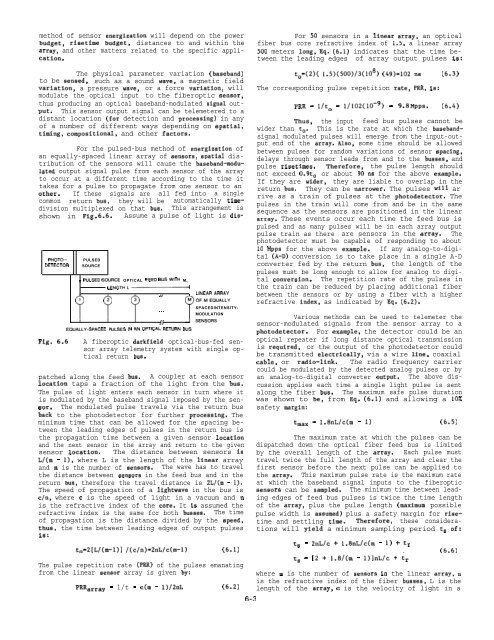
For the pulsed-bus method of energization of<br />
an equally-spaced linear array of sensors, spatial distribution<br />
of the sensors will cause the baaeband-modulated<br />
output signal pulse from each sensor of the array<br />
to occur at a different time according to the time it<br />
takes for a pulse to propagate from one sensor to an -<br />
other. If these signals are all fed into a single<br />
common return bus, they will be automatically timedivision<br />
multiplexed on that bus. This arrangement is<br />
shown in Fig. 6.6. Assume a pulse of light is dis-<br />
‘Warray = l/t = c(m - 1)/2nL (6.2) length of the array, c is the velocity of light in a<br />
For 50 sensors in a linear array, an optical<br />
fiber bus core refractive index of 1.5, a linear array<br />
500 meters long, Eq. (6.1) indicates that the time between<br />
the leading edges of array output pulses is:<br />
to=(2)( l.5)(500)/3(108) (49)=102 ns (6.3)<br />
The corresponding pulse repetition rate, PRR, is:<br />
PRR = l/t. = 1/102(10-9) = 9.8 kfPPS. (6.4)<br />
Thus, the input feed bus pulses cannot be<br />
wider than to. This is the rate at which the basebandsignal<br />
modulated pulses will emerge from the input-output<br />
end of the array. Also, some time should be allowed<br />
between pulses for random variations of sensor spacing,<br />
delays through sensor leads from and to the busses, and<br />
pulse risetimes. Therefore, the pulse length should<br />
not exceed 0.9to or about 90 ns for the above example.<br />
If they are wider, they are liable to overlap in the<br />
return bus. They can be narrower. The pulses will ar -<br />
rive as a train of pulses at the photodetector. The<br />
pulses in the train will come from and be in the same<br />
sequence as the sensors are positioned in the linear<br />
array. These events occur each time the feed bus is<br />
pulsed and as many pulses will be in each array output<br />
pulse train as there are sensors in the array. The<br />
photodetector must be capable of responding to about<br />
10 Mpps for the above example. If any analog-to-digital<br />
(A-D) conversion is to take place in a single A-D<br />
PHOTO– PULSED<br />
OETECTOR SOURCE<br />
converter fed by the return bus, the length of the<br />
pulses must be long enough to allow for analog to digital<br />
conversion. The repetition rate of the pulses in<br />
I r PULSED SOURCE OPTICAL FEEO BUSwlTH M. l<br />
LENGTHL~<br />
the train can be reduced by placing additional fiber<br />
)J LINEAR ARRAY between the sensors or by using a fiber with a higher<br />
refractive index, as indicated by Eq. (6.2).<br />
SPACEDINTENSITY-<br />
. . .<br />
MODULATION<br />
{r<br />
)J<br />
Various methods can be used to telemeter the<br />
sensor-modulated signals from the sensor array to a<br />
EQUALLY-SPACEO PULSES IN AN OPTICAL RETURN SUS<br />
photodetector. For example, the detector could be an<br />
A fiberoptic darkfield optical-bus-fed sensor<br />
array telemetry system with single op-<br />
is required, or the output of the photodetector could<br />
optical repeater if long distance optical transmission<br />
tical return bus.<br />
be transmitted electrically, via a wire line, coaxial<br />
cable, or radio-link. The radio frequency carrier<br />
could be modulated by the detected analog pulses or by<br />
A coupler at each sensor an analog-to-digital converter output. The above discussion<br />
applies each time a single light pulse is sent<br />
along the fiber bus. The maximum safe pulse duration<br />
was shown to be, from Eq. (6.1) and allowing a 10%<br />
The modulated pulse travels via the return bus safety margin:<br />
‘msx = 1.8nL/c(m - 1) (6.5)<br />
The maximum rate at which the pulses can be<br />
dispatched down the optical fiber feed bus is limited<br />
The distance between sensors is by the overall length of the array. Each pulse must<br />
travel twice the full length of the array and clear the<br />
The wave has to travel first sensor before the next pulse can be applied to<br />
the array. This maximum pulse rate is the maximum rate<br />
at which the baseband signal inputs to the fiberoptic<br />
aensors can be sampled. The minimum time between leading<br />
edges of feed bus pulses is twice the time length<br />
of the array, plus the pulse length (maximum possible<br />
The time pulse width is assumed) plus a safety margin for risetime<br />
and settling time. Therefore, these considerations<br />
the time between leading edges of output pulses<br />
will yield a minimum sampling period ts of:<br />
to=2[L/(m-1)] /(c/n)=2nL/c(m-1) (6.1)<br />
t+ = 2nL/c + 1.8nL/c(m - 1) + tr<br />
(6.6)<br />
ts = [2 + 1.8/(m - l)]nL/c + tr<br />
where m is the number of aenaors in the linear array, n<br />
is the refractive index of the fiber busses, L is the<br />
The physical parameter variation (baseband)<br />
to be sensed, such as a sound wave, a magnetic field<br />
variation, a pressure wave, or a force variation, will<br />
modulate the optical input to the fiberoptic sensor,<br />
thus producing an optical baseband-modulated signal output.<br />
This sensor output signal can be telemetered to a<br />
distant location (for detection and processing) in any<br />
of a number of different ways depending on spatial,<br />
timing, compositional, and other factors.<br />
Fig. 6.6<br />
patched along the feed bus.<br />
location taps a fraction of the light from the bus.<br />
The pulse of light enters each sensor in turn where it<br />
is modulated by the baseband signal imposed by the sensor.<br />
bsck to the photodetector for further processing. The<br />
minimum time that can be allowed for the spacing between<br />
the leading edges of pulses in the return bus is<br />
the propagation time between a given sensor location<br />
and the next sensor in the array and return to the given<br />
sensor location.<br />
L/(m - 1), where L is the length of the linear array<br />
and m is the number of sensors.<br />
the distance between aensors in the feed bus and in the<br />
return bus, therefore the travel distance is 2L/(m - 1).<br />
The speed of propagation of a lightwave in the bus is<br />
c/n, where c is the speed of light in a vacuum and n<br />
is the refractive index of the core. It iS assumed the<br />
refractive index is the same for both busses.<br />
of propagation is the distance divided by the speed,<br />
thus,<br />
is:<br />
The pulse repetition rate (PRR) of the pulses emanating<br />
from the linear senaor array is given by:<br />
6-3


