

FIBEROPTIC SENSOR TECHNOLOGY HANDBOOK
FIBEROPTIC SENSOR TECHNOLOGY HANDBOOK
FIBEROPTIC SENSOR TECHNOLOGY HANDBOOK

Create successful ePaper yourself
Turn your PDF publications into a flip-book with our unique Google optimized e-Paper software.
-2 3 4 5 6 7 8 9 10 11 12<br />
BEND RADIUS (mm)<br />
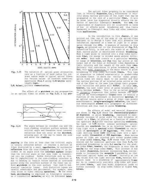
Fig. 2.20 The variation of optical power attenuation<br />
rate as a function of bend radius for constant<br />
radius bends in typical optical fibers<br />
for various values of constant numerical<br />
apertures (N.A.) using 0.83-micron wavelength<br />
light.<br />
C.H. Bulmer, private communication.<br />
Fig. 2.21<br />
The effect of a microbend on ray propagation<br />
in an optical fiber is shown in Fig. 2.21. A ray pro-<br />
+==2si-<br />
The angle between an incident ray and the<br />
core-cladding interface surface exceeds the<br />
critical angle and therefore total internal<br />
reflection does not occur at the microbend,<br />
allowing part of the ray to leave the core<br />
and enter the cladding.<br />
pagating in the core at less than the critical angle<br />
is totally reflected before it reaches a section of<br />
fiber distorted by a small imperfection. On successive<br />
reflections from the core-cladding interface it is incident<br />
at an angle with the interface surface larger<br />
than the critical angle so that some light is transmitted<br />
into the cladding. Random distortions such as this,<br />
due to imperfections in the core-cladding interface or<br />
due to bending or tensile forces exerted at scattered<br />
points along the interface surface of the fiber can induce<br />
microbends in the core surface that lead to substantial<br />
cumulative losses. Such distortion losses are<br />
usually undesirable and detrimental, for example, when<br />
they arise in fiber cabling operations. on the other<br />
hand, microbending is employed in fiberoptic sensors<br />
as a transduction mechanism, as will be discussed later.<br />
2-1o<br />
The optical fiber property to be considered<br />
last is velocity dispersion, i.e. , differences in velocity<br />
among various portions of the light that may be<br />
propagated in the core of a particular fiber. It will<br />
be shown later how dispersion directly affects the behavior<br />
of specific fiberoptic sensors. For now, the<br />
significance of dispersion will be illustrated in terms<br />
of how it affects pulse broadening and thus limits<br />
bandwidth in fiberoptic data links and other communication<br />
applications.<br />
In the introduction to this chapter, it was<br />
pointed out that one of the aims of the optical-fiber<br />
designer is to design a fiber that will preserve the<br />
information impressed on a beam of light as it propagates<br />
through its core. A measure of success in this<br />
regard, as pointed out in the discussion of Fig. 2.2,<br />
Subsection 2.1.1, is how well the width of an individual<br />
narrow pulse is maintained without broadening.<br />
When a light pulse is injected into a step-index multimode<br />
fiber, its energy is divided among several different<br />
modes. Each mode travels at a particular velocity,<br />
or range of velocities, and thua they may arrive at the<br />
output end of the fiber at different times depending on<br />
their velocity and the length of the path they take.<br />
Obviously this contributes to pulse broadening and, in<br />
fact, this modal dispersion is the major source of pulse<br />
broadening in step-index multimode fibers. This type<br />
of dispersion is reduced substantially in graded-index<br />
multimode fibers in which the various modal propagation<br />
times are nearly equal to one another and thus<br />
the various portions of an injected pulse arrive at the<br />
end of the fiber at the same time though their propagation<br />
velocities and paths will differ. In this case,<br />
however, the next lower level of pulse broadening effects<br />
becomes evident. This is the so-called material<br />
or chromatic dispersion that occurs because the velocity<br />
of an electromagnetic (light) wave is usually a<br />
function of the wavelength in dielectric material. If<br />
an optical source emits a pulse of other than purely<br />
monochromatic (single-wavelength) radiation, the various<br />
wavelengths preaent will propagate at different<br />
velocities and thus lead to pulse broadening.<br />
The effects of modal and material dispersion<br />
are shown in Fig. 2.22 where the theoretically-predicted<br />
dipersion or pulse broadening, expressed in nanoseconds<br />
increase of pulse width for each kilometer of<br />
travel in a fiber, is plotted as a function of numerical<br />
aperture (N.A.) for various operating conditions.<br />
Two types of 0.85 micron nominal wavelength optical<br />
sources are considered. One is an injection laser emitting<br />
light with a apectral width (linewidth or variation<br />
of wavelength) of 20 Angstroms. The other is a<br />
light emitting diode (LED) emitting light with a spectral<br />
width (linewidth) of 350 Angstroms. When narrow<br />
pulses of light are injected into either graded-index<br />
or step-index fibers, Fig. 2.22 shows that for laser<br />
sources and for numerical apertures less than 0.15, the<br />
predicted broadening is only 0.2 nsec/km for the graded-index<br />
fiber, however, the dispersion is more than 10<br />
nsecfkm for the step-index fiber. This increase is due<br />
to modal diaperaion, because increasing N.A. corresponds<br />
to increasing the waveguide V-parameter so that<br />
additional optical modes are allowed. Initially at low<br />
N.A. values with the light emitting diode, material dispersion<br />
leads to a broadening of approximately 5 nsec<br />
per km in commercially available step-index and graded-index<br />
fibers,<br />
further increases<br />
values.<br />
and then modal dispersion leads to<br />
in step-index fibers at higher N.A.


