

FIBEROPTIC SENSOR TECHNOLOGY HANDBOOK
FIBEROPTIC SENSOR TECHNOLOGY HANDBOOK
FIBEROPTIC SENSOR TECHNOLOGY HANDBOOK

Create successful ePaper yourself
Turn your PDF publications into a flip-book with our unique Google optimized e-Paper software.
(a)<br />
&<br />
A<br />
FREE RUNNING<br />
Av = 5MHZ<br />
(c)<br />
(b)<br />
11<br />
I<br />
u<br />
0.2 0 0.2 0.2 0 0.2<br />
A<br />
A<br />
SATELLITE MODES<br />
Av = 0.02GHz Av= .12GHz<br />
0.04% 0.06%<br />
FEEDBACK FEEDBACK<br />
(<br />
606<br />
A<br />
MULTIMODES<br />
Av = 5GHZ<br />
1.5%<br />
FEEDBACK<br />
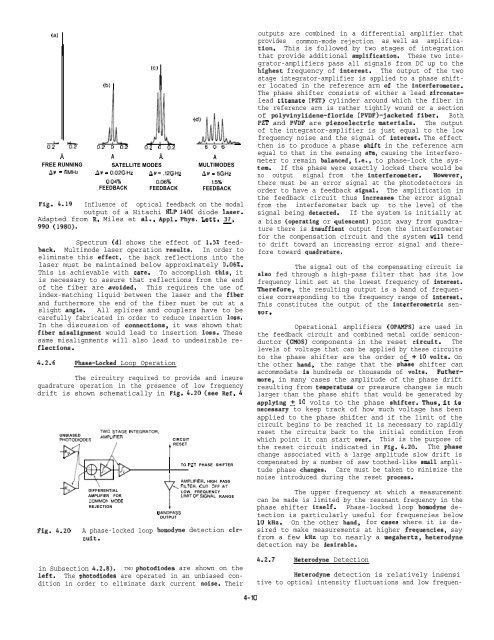
Fig. 4.19 Influence of optical feedback on the modal<br />
output of a Hitachi HLP 1400 diode laser.<br />
Adapted from R. Miles et al., Appl. Phys. Lett. ~,<br />
990 (1980).<br />
Spectrum (d) shows the effect of 1.5% feedback.<br />
Multimode laser operation results. In order to<br />
eliminate this effect, the back reflections into the<br />
laser must be maintained below approximately 0.06%.<br />
This is achievable with care. To accomplish this, it<br />
is necessary to assure that reflections from the end<br />
of the fiber are avoided. This requires the use of<br />
index-matching liquid between the laser and the fiber<br />
and furthermore the end of the fiber must be cut at a<br />
slight angle. All splices and couplers have to be<br />
carefully fabricated in order to reduce insertion loss.<br />
In the discussion of connections, it was shown that<br />
fiber misalignment would lead to insertion loss. These<br />
same misalignments will also lead to undesirable reflections.<br />
4.2.6 Phase-Locked Loop Operation<br />
The circuitry required to provide and insure<br />
quadrature operation in the presence of low frequency<br />
drift is shown schematically in Fig. 4.20 (see Ref. 4<br />
Fig. 4.20<br />
TWO STAGE INTEGRATOR,<br />
UNBIASED<br />
AMPLIFIER.<br />
PHOTODIODES<br />
CIRCUIT<br />
RESET<br />
KO<br />
M<br />
/)+“+ \<br />
/ I<br />
TO PZT PHASE SHIFTER<br />
J L 1<br />
-<br />
w /<br />
AMPLIFIER, HIGH PASS<br />
/<br />
..,FILTER. CUT OFFAT<br />
KD<br />
DIFFERENTIAL<br />
LOW FREQUENCY<br />
AMPLIFIER FOR<br />
LIMIT OF SIGNAL RANGE<br />
COMMON MODE<br />
REJECTION<br />
A phase-locked loop<br />
Cuit.<br />
t<br />
BANDPASS<br />
OUTPUT<br />
homodyne detection cirin<br />
Subsection 4.2.8). TWO photodiodea are shown on the<br />
left. The photodiodes are operated in an unbiased condition<br />
in order to eliminate dark current noise. Their<br />
outputs are combined in a differential amplifier that<br />
provides common-mode rejection as well as amplification.<br />
This is followed by two stages of integration<br />
that provide additional amplification. These two integrator-amplifiers<br />
pass all signals from DC up to the<br />
higheat frequency of interest. The output of the two<br />
stage integrator-amplifier is applied to a phase shifter<br />
located in the reference arm of. the interferometer.<br />
The phase shifter consists of either a lead zirconatelead<br />
titanate (PZT) cylinder around which the fiber in<br />
the reference arm is rather tightly wound or a section<br />
of polyvinylidene-floride (PVDF)-jacketed fiber. Both<br />
PZT and PVDF are piezoelectric materials. The output<br />
of the integrator-amplifier is just equal to the low<br />
frequency noise and the signal of interest. The effect<br />
then is to produce a phase ahift in the reference arm<br />
equal to that in the sensing anm, causing the interferometer<br />
to remain balanced, i.e., to phase-lock the system.<br />
If the phase were exactly locked there would be<br />
no output signal from the interferometer. However,<br />
there must be an error signal at the photodetectors in<br />
order to have a feedback signal. The amplification in<br />
the feedback circuit thus increaaes the error signal<br />
from the interferometer back up to the level of the<br />
signal being detected. If the system is initially at<br />
a bias (operating or quiescent) point away from quadrature<br />
there is insuffient output from the interferometer<br />
for the compensation circuit and the system till tend<br />
to drift toward an increasing error signal and therefore<br />
toward quadrature.<br />
The signal out of the compensating circuit is<br />
alao fed through a high-pass filter that has its low<br />
frequency limit set at the lowest frequency of interest.<br />
Therefore, the resulting output is a band of frequencies<br />
corresponding to the frequency range of interest.<br />
This constitutes the output of the interferometric sensor.<br />
Operational amplifiers (OPAMPS) are used in<br />
the feedback circuit and combined metal oxide semiconductor<br />
(CMOS) components in the reset circuit. The<br />
levels of voltage that can be applied by these circuits<br />
to the phase shifter are the order of + 10 volts. On<br />
the other hand, the range that the ph~se shifter can<br />
accommodate ia hundreds or thousands of volts. Furthermore,<br />
in many cases the amplitude of the phase drift<br />
resulting from temperatuze or pressure changes is much<br />
larger than the phase shift that would be generated by<br />
applying ~ 10 volts to the phase shifter. Thus, it is<br />
necesaary to keep track of how much voltage has been<br />
applied to the phase shifter and if the limit of the<br />
circuit begins to be reached it is necessary to rapidly<br />
reset the circuits back to the initial condition from<br />
which point it can start over. This is the purpose of<br />
the reset circuit indicated in Fig. 4.20. The phaae<br />
change associated with a large amplitude slow drift is<br />
compensated by a number of saw toothed-like amall amplitude<br />
phase changes. Care must be taken to minimize the<br />
noise introduced during the reset process.<br />
The upper frequency at which a measurement<br />
can be made is limited by the resonant frequency in the<br />
phase shifter itself. Phase-locked loop homodyne detection<br />
is particularly useful for frequencies below<br />
10 kHz. On the other hand, for casea where it is desired<br />
to make measurements at higher frequencies, say<br />
from a few kHz up to nearly a megahertz, heterodyne<br />
detection may be desirable.<br />
4.2.7 Heterodyne Detection<br />
Heterodyne detection is relatively insensi -<br />
tive to optical intensity fluctuations and low frequen-<br />
4-10


