You also want an ePaper? Increase the reach of your titles
YUMPU automatically turns print PDFs into web optimized ePapers that Google loves.
A<br />
ENGINEERING<br />
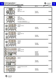
BEARING REACTIONS<br />
Calculation equations<br />
Symbols used<br />
a e Effective bearing spread mm, in.<br />
A, B, ... Bearing position, used as subscripts<br />
c 1, c 2, ... Linear distance (positive or negative) mm, in.<br />
D pG Pitch diameter of the gear mm, in.<br />
F Applied <strong>for</strong>ce N, lbf<br />
F r Radial bearing load N, lbf<br />
h<br />
Horizontal (used as subscript)<br />
M Moment N-mm, lbf-in.<br />
v<br />
Vertical (used as subscript)<br />
1<br />
Gear mesh angle relative to plane<br />
of reference defined in the figure below<br />
deg, rad<br />
2<br />
3<br />
1<br />
2<br />
3<br />
Plane of<br />
Reference<br />
F aG<br />
Angle of applied <strong>for</strong>ce relative to plane<br />
of reference defined in the figure below<br />
Angle of applied moment relative to plane<br />
of reference defined in the figure below<br />
F sG<br />
F sG<br />
F tG F<br />
F aG F tG<br />
F<br />
Plane of Moment<br />
Bearing A<br />
Fig. 42. Bearing radial reactions.<br />
F rA h<br />
F rA v<br />
c 1<br />
c 2<br />
a e<br />
M<br />
deg, rad<br />
deg, rad<br />
Bearing B<br />
F rB h<br />
F rB v<br />
Centrifugal <strong>for</strong>ce<br />
Centrifugal <strong>for</strong>ce resulting from imbalance in a rotating member:<br />
F c =<br />
=<br />
Shock loads<br />
F w r n 2<br />
8.94 x 10 5<br />
F w r n 2<br />
3.52 x 10 4<br />
(newtons)<br />
(pounds-<strong>for</strong>ce)<br />
It is difficult to determine the exact effect that shock loading has<br />
on bearing life. The magnitude of the shock load depends on the<br />
masses of the colliding bodies, their velocities, and de<strong>for</strong>mations<br />
at impact.<br />
The effect on the bearing depends on how much of the shock is<br />
absorbed between the point of impact and the bearings, as well as<br />
whether the shock load is great enough to cause bearing damage.<br />
It also is dependent on frequency and duration of shock loads.<br />
At a minimum, a suddenly applied load is equivalent to twice its<br />
static value. It may be considerably more than this, depending on<br />
the velocity of impact.<br />
Shock involves a number of variables that generally are not known<br />
or easily determined. There<strong>for</strong>e, it is good practice to rely on<br />
experience. The <strong>Timken</strong> Company has years of experience with<br />
many types of equipment under the most severe loading conditions.<br />
Your <strong>Timken</strong> representative should be consulted on any application<br />
involving unusual loading or service requirements.<br />
Vertical reaction component at bearing position B:<br />
F rB v = 1 c 1 (F sG cos 1 + F tG sin 1) + 1 (DpG - b sin G) F aG cos 1 +c 2 F cos 2 + M cos 3<br />
a e 2<br />
(<br />
Horizontal reaction component at bearing position B:<br />
F rB h = 1 c 1 (F sG sin 1 - F tG cos 1) + 1 (DpG - b sin G) F aG sin 1 +c 2 F sin 2 + M sin 3<br />
a e 2<br />
(<br />
Vertical reaction component at bearing position A:<br />
F rAv = F sG cos 1 + F tG sin 1 + F cos 2 - F rBv<br />
Horizontal reaction component at bearing position A:<br />
F rA h = F sG sin 1 - F tG cos 1 + F sin 2 - F rB h<br />
Resultant radial reaction: F rA = [(F rA v) 2 + (F rA h) 2 ] 1/2 F rB = [(F rB v) 2 + (F rB h) 2 ] 1/2<br />
Resultant axial reaction: F aA = F aG (fixed position) F aB = O (float position)<br />
(<br />
(<br />
42 TIMKEN MACHINE TOOL CATALOG