
You also want an ePaper? Increase the reach of your titles
YUMPU automatically turns print PDFs into web optimized ePapers that Google loves.
Simple Mounting<br />
The evolution of two single-row bearing arrangements <strong>for</strong> spindles,<br />
discussed below, is directly related to the speed requirements and,<br />
consequently, the lubrication modes (see page 56).<br />
TS and TSF Arrangement<br />
The spindle is supported by one bearing at the nose position and a<br />
second one at the tail position. This layout offers the advantage of being<br />
a simple isostatic design that allows easy machining of adjacent parts.<br />
The mounting and setting procedures can be achieved without any<br />
specific tooling.<br />
Static stiffness calculations of the spindle-bearing system allow<br />
the optimum bearing spread to be determined precisely <strong>for</strong> each<br />
mounting, as a function of the overhung value of the spindle nose.<br />
A good approximation, however, is to consider that the distance<br />
between bearing centers should be of two and a half to three times<br />
ENGINEERING<br />
the spindle nose diameter. This represents an optimum value not<br />
only <strong>for</strong> stiffness, but also <strong>for</strong> thermal equilibrium.<br />
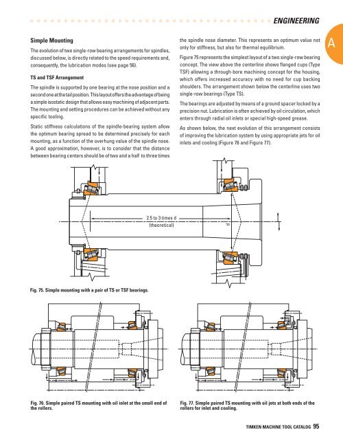
Figure 75 represents the simplest layout of a two single-row bearing<br />
concept. The view above the centerline shows flanged cups (Type<br />
TSF) allowing a through-bore machining concept <strong>for</strong> the housing,<br />
which offers increased accuracy with no need <strong>for</strong> cup backing<br />
shoulders. The arrangement shown below the centerline uses two<br />
single-row bearings (Type TS).<br />
The bearings are adjusted by means of a ground spacer locked by a<br />
precision nut. Lubrication is often achieved by oil circulation, which<br />
enters through radial oil inlets or special high-speed grease.<br />
As shown below, the next evolution of this arrangement consists<br />
of improving the lubrication system by using appropriate jets <strong>for</strong> oil<br />
inlets and cooling (Figure 76 and Figure 77).<br />
A<br />
2.5 to 3 times d<br />
(theoretical)<br />
d<br />
Fig. 75. Simple mounting with a pair of TS or TSF bearings.<br />
Fig. 76. Simple paired TS mounting with oil inlet at the small end of<br />
the rollers.<br />
Fig. 77. Simple paired TS mounting with oil jets at both ends of the<br />
rollers <strong>for</strong> inlet and cooling.<br />
TIMKEN MACHINE TOOL CATALOG 95