
Create successful ePaper yourself
Turn your PDF publications into a flip-book with our unique Google optimized e-Paper software.
Oil Circulation<br />
Many parameters have to be considered in designing an efficient<br />
oil circulation lubrication system:<br />
• Oil characteristics.<br />
• Oil flow rates.<br />
• Oil feed and drain systems.<br />
• Heat dissipation rate of the bearing system.<br />
The latter is affected by factors such as conduction through the<br />
housing walls and convection by the circulating lubricant.<br />
Oil Characteristics<br />
A low-viscosity mineral oil in the range of ISO VG10 to ISO VG22<br />
is generally specified <strong>for</strong> the bearings. This choice will minimize<br />
heat generation, particularly at high speeds, where the lowest<br />
practical viscosity is required. Care must be taken, however, if<br />
gears are used <strong>for</strong> the power transmission because the choice of<br />
the common lubricant will be systematically dictated by the needs<br />
of the gears. High-quality mineral oils having suitable additives<br />
<strong>for</strong> lubricating both the gears and bearings are available with a<br />
relatively low viscosity.<br />
Oil Feed System<br />
Forced-feed oil systems are generally used in the machine tool<br />
industry. In a typical system, oil is pumped from a central reservoir<br />
to each bearing separately. Oil is introduced at the small end of the<br />
rollers and drained away at the large end to take advantage of the<br />
natural pumping action of tapered roller bearings.<br />
Circulating oil allows a continuous regulated oil flow. Apart from<br />
providing the advantages of maximum heat dissipation, it also has<br />
the added benefit of removing any contamination or debris that<br />
could possibly cause bearing wear.<br />
Heat exchangers can be included in a circulating system to reduce<br />
oil inlet temperature and better regulate the running temperature of<br />
the system. Filters of 0.040 mm (0.00157 in.) size also are generally<br />
provided to remove debris.<br />
ENGINEERING<br />
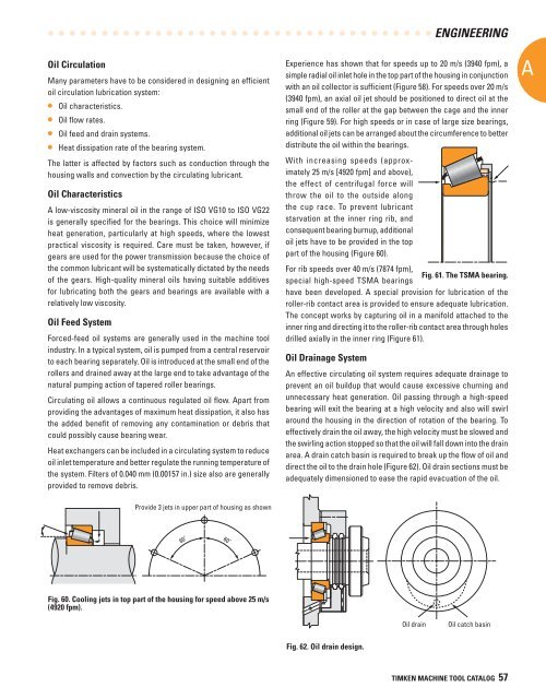
Experience has shown that <strong>for</strong> speeds up to 20 m/s (3940 fpm), a<br />
simple radial oil inlet hole in the top part of the housing in conjunction<br />
with an oil collector is sufficient (Figure 58). For speeds over 20 m/s<br />
(3940 fpm), an axial oil jet should be positioned to direct oil at the<br />
small end of the roller at the gap between the cage and the inner<br />
ring (Figure 59). For high speeds or in case of large size bearings,<br />
additional oil jets can be arranged about the circumference to better<br />
distribute the oil within the bearings.<br />
With increasing speeds (approximately<br />
25 m/s [4920 fpm] and above),<br />
the effect of centrifugal <strong>for</strong>ce will<br />
throw the oil to the outside along<br />
the cup race. To prevent lubricant<br />
starvation at the inner ring rib, and<br />
consequent bearing burnup, additional<br />
oil jets have to be provided in the top<br />
part of the housing (Figure 60).<br />
For rib speeds over 40 m/s (7874 fpm),<br />
Fig. 61. The TSMA bearing.<br />
special high-speed TSMA bearings<br />
have been developed. A special provision <strong>for</strong> lubrication of the<br />
roller-rib contact area is provided to ensure adequate lubrication.<br />
The concept works by capturing oil in a manifold attached to the<br />
inner ring and directing it to the roller-rib contact area through holes<br />
drilled axially in the inner ring (Figure 61).<br />
Oil Drainage System<br />
An effective circulating oil system requires adequate drainage to<br />
prevent an oil buildup that would cause excessive churning and<br />
unnecessary heat generation. Oil passing through a high-speed<br />
bearing will exit the bearing at a high velocity and also will swirl<br />
around the housing in the direction of rotation of the bearing. To<br />
effectively drain the oil away, the high velocity must be slowed and<br />
the swirling action stopped so that the oil will fall down into the drain<br />
area. A drain catch basin is required to break up the flow of oil and<br />
direct the oil to the drain hole (Figure 62). Oil drain sections must be<br />
adequately dimensioned to ease the rapid evacuation of the oil.<br />
A<br />
Provide 3 jets in upper part of housing as shown<br />
60˚<br />
60˚<br />
Fig. 60. Cooling jets in top part of the housing <strong>for</strong> speed above 25 m/s<br />
(4920 fpm).<br />
Oil drain<br />
Oil catch basin<br />
Fig. 62. Oil drain design.<br />
TIMKEN MACHINE TOOL CATALOG 57