- Page 1 and 2:
Timken ® Super Precision Bearings
- Page 3 and 4:
TIMKEN MACHINE TOOL CATALOG TIMKEN.
- Page 5 and 6:
TIMKEN MACHINE TOOL CATALOG BRANDS
- Page 7 and 8:
TIMKEN MACHINE TOOL CATALOG The Qui
- Page 9 and 10:
TIMKEN MACHINE TOOL CATALOG 2 2 2 L
- Page 11 and 12:
TIMKEN MACHINE TOOL CATALOG Inasmuc
- Page 13 and 14:
A ENGINEERING A 12 TIMKEN MACHINE T
- Page 15 and 16:
ENGINEERING A Typical consideration
- Page 17 and 18:
A ENGINEERING TIMKEN ® SUPER PRECI
- Page 19 and 20:
A ENGINEERING Stiffness (relative t
- Page 21 and 22:
A ENGINEERING Load Capacity Some ma
- Page 23 and 24:
A ENGINEERING Precision Tapered Rol
- Page 25 and 26:
A ENGINEERING SELECTING THE APPROPR
- Page 27 and 28:
A ENGINEERING SUPER PRECISION BALL
- Page 29 and 30:
A ENGINEERING High Contact Angle (2
- Page 31 and 32:
A ENGINEERING Timken super precisio
- Page 33 and 34:
A ENGINEERING The overhung distance
- Page 35 and 36:
A ENGINEERING The unique design of
- Page 37 and 38:
ENGINEERING A DETERMINATION OF APPL
- Page 39 and 40:
ENGINEERING A Straight Bevel Gear T
- Page 41 and 42:
A ENGINEERING Worm Gear Tangential
- Page 43 and 44:
A ENGINEERING BEARING REACTIONS Cal
- Page 45 and 46: ENGINEERING A FrA Bearing A Fae Bea
- Page 47 and 48: A ENGINEERING ALTERNATE APPROACH FO
- Page 49 and 50: A ENGINEERING Reliability Life Fact
- Page 51 and 52: A ENGINEERING Load Factor (C l ) Th
- Page 53 and 54: A ENGINEERING SYSTEM LIFE AND WEIGH
- Page 55 and 56: A ENGINEERING SPEED GUIDELINES FOR
- Page 57 and 58: ENGINEERING A LUBRICATION TAPERED R
- Page 59 and 60: A ENGINEERING BALL BEARINGS Even th
- Page 61 and 62: A ENGINEERING OIL Although several
- Page 63 and 64: A ENGINEERING BALL BEARINGS WITH GR
- Page 65 and 66: ENGINEERING A HEAT GENERATION AND D
- Page 67 and 68: A ENGINEERING BALL BEARINGS Heat Ge
- Page 69 and 70: ENGINEERING A TOLERANCES - continue
- Page 71 and 72: ENGINEERING A METRIC SYSTEM BEARING
- Page 73 and 74: ENGINEERING A TOLERANCES - continue
- Page 75 and 76: ENGINEERING A TOLERANCES - continue
- Page 77 and 78: ENGINEERING A TOLERANCES - continue
- Page 79 and 80: ENGINEERING A TOLERANCES - continue
- Page 81 and 82: A ENGINEERING FITTING PRACTICES GEN
- Page 83 and 84: ENGINEERING A PRECISION CLASS TAPER
- Page 85 and 86: ENGINEERING A PRECISION CLASS TAPER
- Page 87 and 88: ENGINEERING A PRECISION CLASS TAPER
- Page 89 and 90: A ENGINEERING SHAFT AND HOUSING CON
- Page 91 and 92: ENGINEERING A SHAFT AND HOUSING TOL
- Page 93 and 94: A ENGINEERING MOUNTING DESIGNS Obta
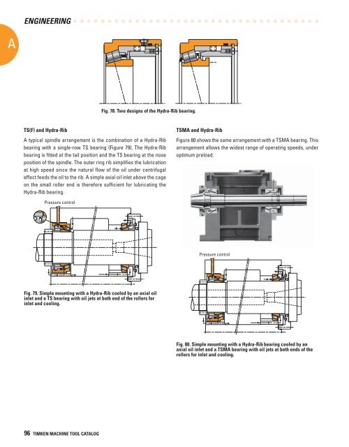
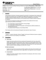
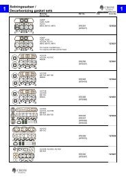
- Page 95: A ENGINEERING TAPERED ROLLER BEARIN
- Page 99 and 100: A ENGINEERING DUPLEX BALL BEARINGS
- Page 101 and 102: A ENGINEERING Spring-Loaded Mountin
- Page 103 and 104: A ENGINEERING During the starting p
- Page 105 and 106: ENGINEERING A NOTES 104 TIMKEN MACH
- Page 107 and 108: B Precision Tapered Roller Bearings
- Page 109 and 110: SUPER PRECISION B ASSEMBLY CODES
- Page 111 and 112: SUPER PRECISION B INTRODUCTION Timk
- Page 113 and 114: SUPER PRECISION TS STYLE PRECISION
- Page 115 and 116: SUPER PRECISION TS STYLE PRECISION
- Page 117 and 118: SUPER PRECISION B TSF STYLE PRECISI
- Page 119 and 120: SUPER PRECISION B TSF STYLE PRECISI
- Page 121 and 122: SUPER PRECISION TXR STYLE METRIC PR
- Page 123 and 124: SUPER PRECISION TSHR STYLE HYDRA-RI
- Page 125 and 126: SUPER PRECISION TSHR STYLE - contin
- Page 127 and 128: SUPER PRECISION TAPERED ROLLER BEAR
- Page 129 and 130: SUPER PRECISION 2 C A BALL BEARINGS
- Page 131 and 132: SUPER PRECISION C Super Precision B
- Page 133 and 134: C Super Precision Ball Bearings Bal
- Page 135 and 136: SUPER PRECISION 2 C A INTRODUCTION
- Page 137 and 138: SUPER PRECISION 2 C MICRON BORE AND
- Page 139 and 140: SUPER PRECISION 2 C A Ultra-Precisi
- Page 141 and 142: SUPER PRECISION 2 Single-Bar Machin
- Page 143 and 144: SUPER PRECISION 2 ULTRA-LIGHT ISO 1
- Page 145 and 146: SUPER PRECISION ULTRA-LIGHT ISO 19
- Page 147 and 148:
SUPER PRECISION 2 C A ULTRA-LIGHT 2
- Page 149 and 150:
SUPER PRECISION 2 ULTRA-LIGHT 2MM93
- Page 151 and 152:
SUPER PRECISION ULTRA-LIGHT ISO 19
- Page 153 and 154:
SUPER PRECISION ULTRA-LIGHT ISO 19
- Page 155 and 156:
SUPER PRECISION 2 C A ULTRA-LIGHT 2
- Page 157 and 158:
SUPER PRECISION 2 ULTRA-LIGHT 2MMV9
- Page 159 and 160:
SUPER PRECISION EXTRA-LIGHT ISO 10
- Page 161 and 162:
SUPER PRECISION EXTRA-LIGHT ISO 10
- Page 163 and 164:
SUPER PRECISION 2 C A EXTRA-LIGHT 2
- Page 165 and 166:
SUPER PRECISION 2 EXTRA-LIGHT 2MM91
- Page 167 and 168:
SUPER PRECISION EXTRA-LIGHT ISO 10
- Page 169 and 170:
SUPER PRECISION EXTRA-LIGHT ISO 10
- Page 171 and 172:
SUPER PRECISION 2 C A EXTRA-LIGHT 2
- Page 173 and 174:
SUPER PRECISION EXTRA-LIGHT 2MMV910
- Page 175 and 176:
SUPER PRECISION EXTRA-LIGHT ISO 10
- Page 177 and 178:
SUPER PRECISION 2 EXTRA-LIGHT ISO 1
- Page 179 and 180:
SUPER PRECISION 2 C A EXTRA-LIGHT 2
- Page 181 and 182:
SUPER PRECISION 2 EXTRA-LIGHT 2MMV9
- Page 183 and 184:
SUPER PRECISION 2 ULTRA-LIGHT ISO 1
- Page 185 and 186:
SUPER PRECISION LIGHT ISO 02 SERIES
- Page 187 and 188:
SUPER PRECISION LIGHT ISO 02 SERIES
- Page 189 and 190:
SUPER PRECISION 2 C A LIGHT 2MM200W
- Page 191 and 192:
SUPER PRECISION LIGHT 2MM200WI ISO
- Page 193 and 194:
SUPER PRECISION LIGHT ISO 02 SERIES
- Page 195 and 196:
SUPER PRECISION MEDIUM ISO 03 SERIE
- Page 197 and 198:
2 C A SUPER PRECISION MEDIUM 2(3)MM
- Page 199 and 200:
SUPER PRECISION MEDIUM ISO 03 SERIE
- Page 201 and 202:
SUPER PRECISION 2 C BALL SCREW SUPP
- Page 203 and 204:
SUPER PRECISION 2 C BALL SCREW SUPP
- Page 205 and 206:
SUPER PRECISION 2 C BALL SCREW SUPP
- Page 207 and 208:
SUPER PRECISION 2 C BALL SCREW SUPP
- Page 209 and 210:
SUPER PRECISION 2 C BALL SCREW SUPP
- Page 211 and 212:
SUPER PRECISION 2 C BALL SCREW SUPP
- Page 213 and 214:
SUPER PRECISION 2 C BALL SCREW SUPP
- Page 215 and 216:
SUPER PRECISION 2 EX-CELL-O SPINDLE
- Page 217 and 218:
SUPER PRECISION BALL BEARING BORE D
- Page 219 and 220:
SUPER PRECISION D FREQUENCY COEFFIC
- Page 221 and 222:
SUPER PRECISION TSF Metric Style FT
- Page 223 and 224:
SUPER PRECISION FREQUENCY COEFFICIE
- Page 225 and 226:
SUPER PRECISION 2MMV9300HX Series F
- Page 227 and 228:
SUPER PRECISION 2MM9100WI Series FT
- Page 229 and 230:
SUPER PRECISION 2MMV9100HX Series F
- Page 231 and 232:
SUPER PRECISION 2MMV99100WN Series
- Page 233 and 234:
SUPER PRECISION 2MM200WI Series FTF
- Page 235 and 236:
SUPER PRECISION 2MM300WI Series FTF
- Page 237 and 238:
SUPER PRECISION FREQUENCY COEFFICIE
- Page 239 and 240:
SUPER PRECISION INCH SYSTEM Class D
- Page 241 and 242:
SUPER PRECISION GEOMETRY FACTORS -
- Page 243 and 244:
SUPER PRECISION BEARING LOCKNUTS To
- Page 245 and 246:
SUPER PRECISION LUBRICATION SPECIFI
- Page 247 and 248:
SUPER PRECISION D A CONVERSION TABL
- Page 249 and 250:
SUPER PRECISION Application Informa
- Page 251 and 252:
SUPER PRECISION INDEX ITEM PRODUCT
- Page 253 and 254:
SUPER PRECISION NOTES D A 252 TIMKE
- Page 255 and 256:
SUPER PRECISION NOTES D A 254 TIMKE
- Page 257 and 258:
SUPER PRECISION NOTES D A 256 TIMKE
- Page 259:
SUPER PRECISION NOTES D A 258 TIMKE