
Create successful ePaper yourself
Turn your PDF publications into a flip-book with our unique Google optimized e-Paper software.
ENGINEERING<br />
A<br />
FrA<br />
Bearing A<br />
Fae<br />
Bearing A<br />
FrA<br />
Design Thrust condition Axial load<br />
Bearing B<br />
Fae<br />
Bearing B<br />
FrB<br />
Design (external axial load, F ae,<br />
onto bearing A)<br />
FrB<br />
F aA = 0.47 F<br />
P OB = F rB<br />
rB<br />
+ F<br />
0.47 F rA 0.47 F ae<br />
rB<br />
≤<br />
+ F ae<br />
K B<br />
K A K B<br />
F aB = 0.47 F rB<br />
K B<br />
F aA = 0.47 F rA<br />
0.47 F rA 0.47 F rB K<br />
><br />
+ F A<br />
ae<br />
K A K B F aB = 0.47 F rA<br />
K A<br />
- Fae<br />
Static equivalent<br />
radial load<br />
<strong>for</strong> F aA < 0.6 F rA / K A<br />
P OA = 1.6 F rA - 1.269 K A F aA<br />
<strong>for</strong> F aA < 0.6 F rA / K A<br />
P OA = 0.5 F rA + 0.564 K A F aA<br />
<strong>for</strong> F aB < 0.6 F rB / K B<br />
P OB = 0.5 F rB + 0.564 K B F aB<br />
<strong>for</strong> F aB < 0.6 F rB / K B<br />
P OB = 1.6 F rB - 1.269 K B F aB<br />
P OA = F rA<br />
Use the values of P O calculated <strong>for</strong> comparison with the static rating (C O), even if P O is less than the radial applied F r.<br />
Where:<br />
F r = applied radial load<br />
F a = net bearing axial load. F aA and F aB calculated from equations<br />
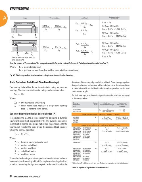
Fig. 43. Static equivalent load equations, single-row tapered roller bearing.<br />
Static Equivalent Radial Load (Two-Row <strong>Bearings</strong>)<br />
The bearing data tables do not include static rating <strong>for</strong> two-row<br />
bearings. The two-row static radial rating can be estimated as:<br />
Where:<br />
C o(2) = 2C o<br />
C o(2) = two-row static radial rating<br />
C o = static radial load rating of a single-row bearing,<br />
type TS, from the same series.<br />
Dynamic Equivalent Radial Bearing Loads (P r )<br />
To calculate the L 10 life, it is necessary to calculate a dynamic<br />
equivalent radial load, designated by P r. The dynamic equivalent<br />
radial load is defined as a single radial load that, if applied to the<br />
bearing, will result in the same life as the combined loading under<br />
which the bearing operates.<br />
P r = XF r + YF a<br />
Where:<br />
P r = dynamic equivalent radial load<br />
F r = applied radial load<br />
F a = applied axial load<br />
X = radial load factor<br />
Y = axial load factor<br />
Tapered roller bearings use the equations based on the number of<br />
rows and type of mounting utilized. For single-row bearings in direct<br />
or indirect mounting, the figure on page 46 can be used based on the<br />
direction of the externally applied axial load. Once the appropriate<br />
design is chosen, review the table and check the thrust condition<br />
to determine which axial load and dynamic equivalent radial load<br />
calculations apply.<br />
For ball bearings, the dynamic equivalent radial load can be found<br />
in the table below.<br />
Bearing<br />
description<br />
(ref.)<br />
Bearing type<br />
and or series<br />
MM9300K<br />
MM9100K<br />
MM200K<br />
MM300K<br />
2MMV9300WI<br />
2MM9300WI<br />
2MMV9100WI<br />
2MM99100WI<br />
2MV9100WI<br />
2MMV200WI<br />
2MM200WI<br />
2MV300WI<br />
Contact<br />
angle<br />
Single-row<br />
and tandem mountings<br />
Double-row<br />
and preload pair<br />
mountings<br />
K T =<br />
F a<br />
K T = Fa<br />
(# of bearings) x C o C o<br />
Radial type ball bearings – use larger of resulting “P r” value (1)<br />
0° P r = F r or<br />
P r = 0.56F r + Y 1F a<br />
Angular contact ball bearings – use larger of resulting “P r” value<br />
2MMV9300HX<br />
2MV9300WI<br />
2MMV9100HX<br />
2MM9100WI<br />
2MV200WI<br />
2MMV300WI<br />
2MM300WI<br />
15°<br />
P r = F r<br />
or<br />
P r = 0.44F r +Y 2F a<br />
2MM9100WO 15° P r = F r<br />
or<br />
P r = 0.44F r + Y 3F a<br />
3MMV9300WI<br />
3MM9300WI<br />
3MMV9100WI<br />
3MM9100WI<br />
3MM99100WI<br />
3MMV200WI<br />
3MM200WI<br />
3MV300WI<br />
3MMV9300HX<br />
3MV9300WI<br />
3MMV9100HX<br />
3MV9100WI<br />
3MV200WI<br />
3MM300WI<br />
3MV300WI<br />
25° P r = F r<br />
or<br />
P r = 0.41F r +0.87F a<br />
P r = F r + 1.20Y 1F a or<br />
P r = 0.78F r + 1.625Y 1F a<br />
P r = F r + 1.124Y 2F a<br />
or<br />
P r = 0.72F r + 1.625Y 2F a<br />
P r = F r + 1.124Y 3F a<br />
or<br />
P r = 0.72F r + 1.625Y 3F a<br />
P r = F r + 0.92F a<br />
or<br />
P r = 0.67F r + 1.41F a<br />
(1) If Pr > Co or Pr > 1/2 Ce consult with your <strong>Timken</strong> representative on Life Calculations.<br />
Table 7. Dynamic equivalent load equations.<br />
44 TIMKEN MACHINE TOOL CATALOG