Create successful ePaper yourself
Turn your PDF publications into a flip-book with our unique Google optimized e-Paper software.
PERMISSIBLE OPERATING SPEED<br />
When determining the permissible operating speeds corresponding<br />
to the bearing preloads used in machine tool spindles, many<br />
influencing factors are involved. Among those considered are<br />
spindle mass and construction, type of mounting, spindle rigidity and<br />
accuracy requirements, spindle loads, service life, type of service<br />
(intermittent or continuous), and method of lubrication.<br />
Bearing temperatures, generally, vary directly with both speed and<br />
load. However, high-speed applications must have sufficient axial<br />
loading on the bearings to prevent heat generation due to rolling<br />
element skidding. The amount of bearing preload is determined<br />
primarily from these operating conditions. At lower speeds, the<br />
operating loads are heavier and the bearing deflections are<br />
greater. There<strong>for</strong>e, the bearing preload must be high enough to<br />
provide adequate bearing rigidity under the heaviest loads and still<br />
maintain reasonable temperatures when the spindle is operated at<br />
high speeds.<br />
TAPERED ROLLER BEARINGS<br />
Measuring Rib Speed<br />
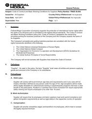
The usual measure of the speed of a tapered roller bearing is the rib<br />
speed, which is the circumferential velocity at the midpoint of the<br />
inner ring large end rib (Figure 54). This may be calculated as:<br />
Rib speed:<br />
Where:<br />
V r =<br />
=<br />
D mn<br />
60000<br />
D mn<br />
12<br />
(m/s)<br />
(ft/min)<br />
D m = mean inner ring large rib diameter mm, in.<br />
n = bearing speed rev/min<br />
Effect of Lubrication on Speed Capability<br />
ENGINEERING<br />
The design of the tapered roller bearing results in a natural pumping<br />
effect on the lubricant, where the lubricant is <strong>for</strong>ced from the small<br />
end of the roller end, heading toward the wider end. As speed<br />
increases, the lubricant begins to move outward due to centrifugal<br />
effects. At excessive speed, the contact between the roller large<br />
ends and the cone’s rib face can become a concern. This is the<br />
primary reason <strong>for</strong> suggestions on the use of oil jets at this large<br />
end, ribbed-cup designs, or high-speed TSMA designs as operating<br />
speeds increase. Refer to the following speed guidelines <strong>for</strong> more<br />
details.<br />
Fig. 55. Pumping effect of<br />
a tapered roller bearing<br />
There are no clear-cut speed limitations <strong>for</strong> tapered roller bearings<br />
since per<strong>for</strong>mance depends on the bearing design and lubrication<br />
system. The guidelines given in the table on page 54 are based on<br />
typical industrial experiences relating to speed and temperature<br />
<strong>for</strong> various types of lubrication systems, with bearings having low<br />
G 1 factor.<br />
<strong>Timken</strong> suggests that testing be per<strong>for</strong>med <strong>for</strong> all new high-speed<br />
applications.<br />
A<br />
Inner ring rib diameter<br />
Fig. 54. Cone rib diameter. The inner ring rib diameter may be scaled<br />
from a print.<br />
TIMKEN MACHINE TOOL CATALOG 53