Create successful ePaper yourself
Turn your PDF publications into a flip-book with our unique Google optimized e-Paper software.
ENGINEERING<br />
(a) (b) (c)<br />
A<br />
2 spacers<br />
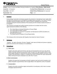
Fig. 71.<br />
Locking devices.<br />
2 screws<br />
spaced<br />
180˚ apart<br />
Soft metal shoe<br />
Nut loose fitted<br />
on thread<br />
SHAFTS<br />
Shafts are preferably made from hardened and ground steel; and,<br />
where suitable, a hardness of 45-50 HRC has been successful.<br />
When designing a spindle or shaft, it is highly desirable to plan so<br />
that it can be ground all over in one setting as a final operation. This<br />
promotes true balance and running accuracy, which are critical in<br />
high-speed applications. Suggested shaft geometry can be found<br />
on pages 89 and 90.<br />
LOCKING DEVICES<br />
In most cases, simple 2TS(F) spindle layouts are adjusted by correct<br />
positioning of the tail bearing cone. A commonly used device is<br />
a precision adjusting nut. A locking device must be provided to<br />
properly maintain the nut after setting: either axially by means of two<br />
screws 180 degrees opposite pinching the threads (Figure 71a), or<br />
radially by pressure of a screw on a soft metal shoe (Figure 71b).<br />
For improved accuracy, a ground spacer in conjunction with a<br />
square-ground spindle shoulder and a locking precision nut also can<br />
be used (Figure 72). Good parallelism of the ground spacer faces as<br />
well as the squareness of the spindle shoulder will ensure a perfect<br />
positioning of the cone backface. This mounting configuration<br />
also offers assurance that the initially defined setting cannot be<br />
interfered with by the final user. Figure 71c shows two different<br />
solutions with ground spacers. Note the practicality of the above<br />
centerline solution, which allows the spacer to both increase or<br />
decrease the initial setting.<br />
A well-known method of providing good spindle alignment,<br />
roundness and backing squareness is to grind the cone seats and<br />
the backing shoulders during the same operation (Figure 73). In this<br />
method, the grinding of the square backing of the adjusting nut (if<br />
any) also can be achieved by locking the nut on its thread. This<br />
eliminates any possible default of the nut due to internal thread<br />
clearance.<br />
Cone seat<br />
Spindle shoulder<br />
Fig. 72. Using ground spacer and spindle shoulder together with a<br />
precision nut <strong>for</strong> improved accuracy.<br />
Adjusting nut<br />
Grinding wheel travel<br />
Locking precision nut<br />
Grinding<br />
wheel<br />
Spacer<br />
Fig. 73. Grinding of cone shaft and backing shoulders.<br />
TIMKEN MACHINE TOOL CATALOG 93