
Create successful ePaper yourself
Turn your PDF publications into a flip-book with our unique Google optimized e-Paper software.
ENGINEERING<br />
A<br />
HEAT GENERATION AND DISSIPATION<br />
TAPERED ROLLER BEARINGS<br />
Heat Generation<br />
Under normal operating conditions, most of the torque and heat<br />
generated by the bearing is due to the elastohydrodynamic losses<br />
at the contact area between rollers and races.<br />
The following equation is used to calculate the heat generated by<br />
the bearing:<br />
Q gen = k 4n M<br />
M = k 1G 1 (nμ) 0.62 (P eq) 0.3<br />
Where:<br />
Q gen = generated heat (W or Btu/min)<br />
M = running torque N.m or lbf-in.<br />
n = rotational speed (RPM)<br />
G 1 = geometry factor from bearing data tables<br />
μ = viscosity at operating temperature (cP)<br />
P eq = dynamic equivalent load (N or lbf)<br />
k 1 = bearing torque constant<br />
= 2.56 x 10 -6 <strong>for</strong> M in N-m<br />
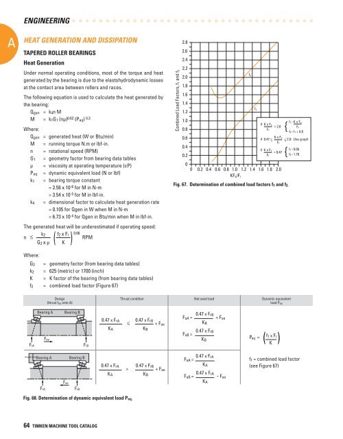
Fig. 67. Determination of combined load factors f 1 and f 2.<br />
= 3.54 x 10 -5 <strong>for</strong> M in lbf-in.<br />
k 4 = dimensional factor to calculate heat generation rate<br />
= 0.105 <strong>for</strong> Qgen in W when M in N-m<br />
= 6.73 x 10 -4 <strong>for</strong> Qgen in Btu/min when M in lbf-in.<br />
The generated heat will be underestimated if operating speed:<br />
n<br />
k 2<br />
( f2 x ) Fr 0.66 RPM<br />
G 2 x μ K<br />
Where:<br />
G 2 = geometry factor (from bearing data tables)<br />
k 2 = 625 (metric) or 1700 (inch)<br />
K = K factor of the bearing (from bearing data tables)<br />
f 2 = combined load factor (Figure 67)<br />
Design<br />
(thrust f ae onto A)<br />
Thrust condition Net axial load Dynamic equivalent<br />
load P eq<br />
Bearing A Bearing B<br />
F aA = 0.47 x FrB + F<br />
0.47 x F ae<br />
rA 0.47 x F rB<br />
≤<br />
+ Fae<br />
K B<br />
K A K B<br />
0.47 x FrB<br />
F aB =<br />
K B<br />
P eq =<br />
( f1 x )<br />
Fr Fae<br />
K<br />
FrA<br />
FrB<br />
Bearing A<br />
Bearing B<br />
0.47 x FrA<br />
F aA =<br />
0.47 x F rA<br />
><br />
0.47 x F rB + Fae<br />
K A<br />
K A<br />
K B<br />
F aB = 0.47 x FrA - F ae<br />
Fae<br />
K A<br />
FrA<br />
FrB<br />
Combined Load Factors, f1 and f2<br />
2.8<br />
2.6<br />
2.4<br />
2.2<br />
2.0<br />
1.8<br />
1.6<br />
1.4<br />
1.2<br />
1.0<br />
0.8<br />
0.6<br />
0.4<br />
0.2<br />
0<br />
0 0.2 0.4 0.6 0.8 1.0 1.2 1.4 1.6 1.8 2.0<br />
KF a /F r<br />
f 2<br />
f 1<br />
if K x Fa<br />
> 2.0<br />
Fr<br />
if K x Fa<br />
= 0.47<br />
Fr<br />
f1 = K x Fa<br />
Fr<br />
{<br />
f2 = f1 + 0.8<br />
K x Fa<br />
if 0.47 < < 2.0: Use graph<br />
- Fr -<br />
{<br />
f1 = 0.06<br />
f2 = 1.78<br />
f 1 = combined load factor<br />
(see Figure 67)<br />
64 TIMKEN MACHINE TOOL CATALOG