Local polarization dynamics in ferroelectric materials
Local polarization dynamics in ferroelectric materials
Local polarization dynamics in ferroelectric materials
Create successful ePaper yourself
Turn your PDF publications into a flip-book with our unique Google optimized e-Paper software.
Rep. Prog. Phys. 73 (2010) 056502<br />
‘threshold’ doma<strong>in</strong> nucleation is similar to the well-known where<br />
first order phase transition (compare figure 31(e) with the<br />
well-known dependence of the free energy profile on the order<br />
parameter for first order <strong>ferroelectric</strong>s).<br />
In the thermally <strong>in</strong>duced nucleation limit, the doma<strong>in</strong><br />
nucleation process is analyzed as a thermally activated motion<br />
<strong>in</strong> the phase space of the system along the m<strong>in</strong>imum energy<br />
path connect<strong>in</strong>g the orig<strong>in</strong> and one of the local m<strong>in</strong>ima. The<br />
relaxation time necessary for the stable doma<strong>in</strong> formation<br />
at U cr is maximal and the critical slow<strong>in</strong>g down appears<br />
<strong>in</strong> accordance with the general theory of phase transitions.<br />
With<strong>in</strong> the framework of the activation rate theory, the doma<strong>in</strong><br />
nucleation takes place at a higher activation voltage U a<br />
determ<strong>in</strong>ed from the condition (U a ) = E a , correspond<strong>in</strong>g<br />
to the activation time τ = τ 0 exp(E a /k B T). For <strong>in</strong>stance,<br />
the activation energy E a = 20k B T corresponds to a relatively<br />
fast nucleation time τ ∼ 10 −3 s for phonon relaxation time<br />
τ 0 = 10 −12 s, while the condition E a 2k B T corresponds to<br />
‘<strong>in</strong>stant’ or thermal nucleation.<br />
×<br />
The difference between the voltages correspond<strong>in</strong>g to<br />
the formation of a saddle po<strong>in</strong>t and a stable doma<strong>in</strong>, U S −<br />
U cr , determ<strong>in</strong>es the width of the thermodynamic hysteresis<br />
loop (see figures 31(e)–(g)). More realistic models of<br />
piezoresponse hysteresis loop formation consider doma<strong>in</strong> wall<br />
p<strong>in</strong>n<strong>in</strong>g effects. In the weak p<strong>in</strong>n<strong>in</strong>g limit, the doma<strong>in</strong><br />
growth <strong>in</strong> the forward direction is assumed to follow the<br />
thermodynamic energy m<strong>in</strong>imum, while with decreas<strong>in</strong>g bias,<br />
the doma<strong>in</strong> rema<strong>in</strong>s stationary due to doma<strong>in</strong> wall p<strong>in</strong>n<strong>in</strong>g<br />
by lattice and atomic defects. For stronger p<strong>in</strong>n<strong>in</strong>g, the<br />
doma<strong>in</strong> size is limited by the wall mobility <strong>in</strong> the tip field<br />
and <strong>ferroelectric</strong> (as, e.g., studied for doma<strong>in</strong> wall dynamic<br />
by Molotskii <strong>in</strong> [311]), and the full analysis of this problem<br />
rema<strong>in</strong>s the matter of future research.<br />
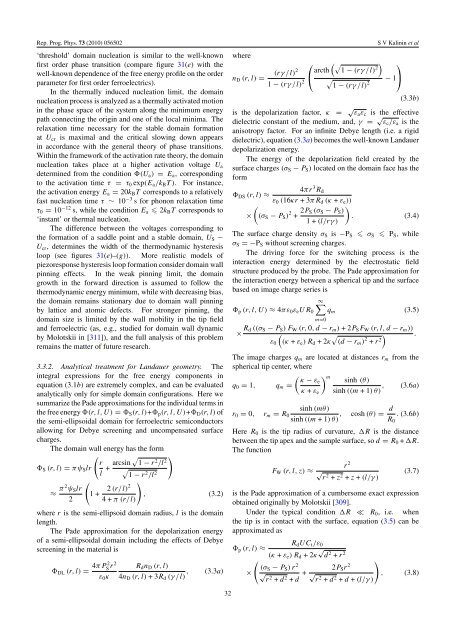
3.3.2. Analytical treatment for Landauer geometry. The<br />
<strong>in</strong>tegral expressions for the free energy components <strong>in</strong><br />
equation (3.1b) are extremely complex, and can be evaluated<br />
analytically only for simple doma<strong>in</strong> configurations. Here we<br />
summarize the Pade approximations for the <strong>in</strong>dividual terms <strong>in</strong><br />
the free energy (r, l, U) = S (r, l)+ p (r,l,U)+ D (r, l) of<br />
the semi-ellipsoidal doma<strong>in</strong> for <strong>ferroelectric</strong> semiconductors<br />
allow<strong>in</strong>g for Debye screen<strong>in</strong>g and uncompensated surface<br />
charges.<br />
The doma<strong>in</strong> wall energy has the form<br />
(<br />
r<br />
S (r, l) = πψ S lr<br />
l + arcs<strong>in</strong> √ )<br />
1 − r 2 /l<br />
√ 2<br />
1 − r2 /l 2<br />
(<br />
)<br />
≈ π 2 ψ S lr<br />
1+ 2 (r/l)2 , (3.2)<br />
2 4+π (r/l)<br />
where r is the semi-ellipsoid doma<strong>in</strong> radius, l is the doma<strong>in</strong><br />
length.<br />
The Pade approximation for the de<strong>polarization</strong> energy<br />
of a semi-ellipsoidal doma<strong>in</strong> <strong>in</strong>clud<strong>in</strong>g the effects of Debye<br />
screen<strong>in</strong>g <strong>in</strong> the material is<br />
DL (r, l) = 4πP2 S r2 R d n D (r, l)<br />
ε 0 κ 4n D (r, l) +3R d (γ/l) , (3.3a) ×<br />
32<br />
n D (r, l) =<br />
⎛ (√ )<br />
(rγ/l)2 ⎝ arcth 1 − (rγ/l)<br />
2<br />
1 − (rγ/l) 2 √<br />
1 − (rγ/l)<br />
2<br />
S V Kal<strong>in</strong><strong>in</strong> et al<br />
⎞<br />
− 1⎠<br />
(3.3b)<br />
is the de<strong>polarization</strong> factor, κ = √ ε a ε c is the effective<br />
dielectric constant of the medium, and, γ = √ ε c /ε a is the<br />
anisotropy factor. For an <strong>in</strong>f<strong>in</strong>ite Debye length (i.e. a rigid<br />
dielectric), equation (3.3a) becomes the well-known Landauer<br />
de<strong>polarization</strong> energy.<br />
The energy of the de<strong>polarization</strong> field created by the<br />
surface charges (σ S − P S ) located on the doma<strong>in</strong> face has the<br />
form<br />
4πr 3 R d<br />
DS (r, l) ≈<br />
ε 0 (16κr +3πR d (κ + ε e ))<br />
(<br />
(σ S − P S ) 2 + 2P S (σ S − P S )<br />
1+(l/rγ)<br />
)<br />
. (3.4)<br />
The surface charge density σ S is −P S σ S P S , while<br />
σ S =−P S without screen<strong>in</strong>g charges.<br />
The driv<strong>in</strong>g force for the switch<strong>in</strong>g process is the<br />
<strong>in</strong>teraction energy determ<strong>in</strong>ed by the electrostatic field<br />
structure produced by the probe. The Pade approximation for<br />
the <strong>in</strong>teraction energy between a spherical tip and the surface<br />
based on image charge series is<br />
p (r, l, U) ≈ 4πε 0 ε e UR 0<br />
∞ ∑<br />
m=0<br />
q m (3.5)<br />
× R d ((σ S − P S ) F W (r, 0,d − r m ) +2P S F W (r, l, d − r m ))<br />
ε 0<br />
(<br />
(κ + ε e ) R d +2κ √ (d − r m ) 2 + r 2 ) .<br />
The image charges q m are located at distances r m from the<br />
spherical tip center, where<br />
( ) κ − m εe s<strong>in</strong>h (θ)<br />
q 0 = 1, q m =<br />
κ + ε e s<strong>in</strong>h ((m +1) θ) , (3.6a)<br />
r 0 = 0, r m = R 0<br />
s<strong>in</strong>h (mθ)<br />
s<strong>in</strong>h ((m +1) θ) ,<br />
cosh (θ) = d R 0<br />
. (3.6b)<br />
Here R 0 is the tip radius of curvature, R is the distance<br />
between the tip apex and the sample surface, so d = R 0 + R.<br />
The function<br />
F W (r, l, z) ≈<br />
r 2<br />
√<br />
r2 + z 2 + z + (l/γ)<br />
(3.7)<br />
is the Pade approximation of a cumbersome exact expression<br />
obta<strong>in</strong>ed orig<strong>in</strong>ally by Molotskii [309].<br />
Under the typical condition R ≪ R 0 , i.e. when<br />
the tip is <strong>in</strong> contact with the surface, equation (3.5) can be<br />
approximated as<br />
R d UC t /ε 0<br />
p (r, l) ≈<br />
(κ + ε e ) R d +2κ √ d 2 + r<br />
(<br />
2<br />
(σ S − P S ) r 2<br />
√<br />
r2 + d 2 + d + 2P S r 2<br />
√<br />
r2 + d 2 + d + (l/γ)<br />
)<br />
, (3.8)


