IP 55 Modular Cabinets
IP 55 Modular Cabinets
IP 55 Modular Cabinets

Create successful ePaper yourself
Turn your PDF publications into a flip-book with our unique Google optimized e-Paper software.
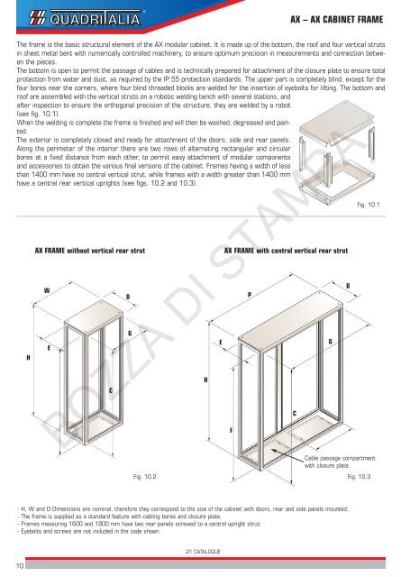
AX – AX CABINET FRAME<br />
The frame is the basic structural element of the AX modular cabinet. It is made up of the bottom, the roof and four vertical struts<br />
in sheet metal bent with numerically controlled machinery, to ensure optimum precision in measurements and connection between<br />
the pieces.<br />
The bottom is open to permit the passage of cables and is technically prepared for attachment of the closure plate to ensure total<br />
protection from water and dust, as required by the <strong>IP</strong> <strong>55</strong> protection standards. The upper part is completely blind, except for the<br />
four bores near the corners, where four blind threaded blocks are welded for the insertion of eyebolts for lifting. The bottom and<br />
roof are assembled with the vertical struts on a robotic welding bench with several stations, and<br />
after inspection to ensure the orthogonal precision of the structure, they are welded by a robot<br />
(see fig. 10.1).<br />
When the welding is complete the frame is finished and will then be washed, degreased and painted.<br />
The exterior is completely closed and ready for attachment of the doors, side and rear panels.<br />
Along the perimeter of the interior there are two rows of alternating rectangular and circular<br />
bores at a fixed distance from each other, to permit easy attachment of modular components<br />
and accessories to obtain the various final versions of the cabinet. Frames having a width of less<br />
than 1400 mm have no central vertical strut, while frames with a width greater than 1400 mm<br />
have a central rear vertical uprights (see figs. 10.2 and 10.3).<br />
H<br />
AX FRAME without vertical rear strut<br />
W<br />
E<br />
C<br />
D<br />
G<br />
H<br />
E<br />
AX FRAME with central vertical rear strut<br />
P<br />
Fig. 10.1<br />
BOZZA DI STAMPA<br />
F<br />
Cable passage compartment<br />
with closure plate.<br />
Fig. 10.2 Fig. 10.3<br />
C<br />
G<br />
D<br />
- H, W and D Dimensions are nominal, therefore they correspond to the size of the cabinet with doors, rear and side panels mounted;<br />
- The frame is supplied as a standard feature with cabling bores and closure plate;<br />
- Frames measuring 1600 and 1800 mm have two rear panels screwed to a central upright strut;<br />
- Eyebolts and screws are not included in the code shown.<br />
10<br />
21 CATALOGUE