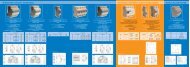
IP 55 Modular Cabinets
IP 55 Modular Cabinets
IP 55 Modular Cabinets

Create successful ePaper yourself
Turn your PDF publications into a flip-book with our unique Google optimized e-Paper software.
UTZ, KIT TO JOIN CABINETS IN BATTERIES<br />
AZ series cabinets may be joined together at the sides, with<br />
the positioning of a rectangular frame between them, as shown<br />
in Fig. 67.1<br />
A gasket is mounted on both sides of the pre-bored frame,<br />
which is then positioned on one of the cabinets and attached<br />
with screws. The other cabinet is then placed near the frame,<br />
H<br />
ASSEMBLY INSTRUCTIONS:<br />
B<br />
A<br />
D<br />
Fig. 67.1<br />
- Mount the gaskets supplied on both sides;<br />
- Insert the tubular piece on the side of the frame of one of<br />
the two cabinets and centre it with the screws;<br />
- Bring the other cabinet into contact and take care to pass the<br />
screws;<br />
- Mount the two plates shown in figures 67.3 and 67.4 from<br />
both sides, at about half the distance of the vertical strut.<br />
- Assemble diagonally (from bottom to top) the two squares<br />
shown in Fig. 67.2;<br />
- Tighten all of the flanged nuts of the tubular piece and the<br />
plates.<br />
taking care to match the bores, and is then attached.<br />
The UTZ code includes not only the frame, but also the<br />
bored junction plates, the gasket and the screws necessary<br />
for attachment and assembly of the plates. The plates<br />
inside the vertical struts are used only and exclusively<br />
to avoid rotation of the strut once the tubular frame<br />
screws have been tightened. They therefore have no function<br />
of mechanical reinforcement of the cabinet itself.<br />
CODES AND CHARACTERISTIC FRAME DIMENSIONS<br />
Fig. 67.2 Fig. 67.3<br />
Fig. 67.4<br />
21 CATALOGUE<br />
Nominal<br />
Dimensions<br />
Characteristics<br />
code H D B A<br />
UTZ184 1800 400 1758 268<br />
UTZ185 1800 500 1758 368<br />
UTZ186 1800 600 1758 468<br />
UTZ188 1800 800 1758 668<br />
UTZ18A 1800 1000 1758 868<br />
UTZ204 2000 400 1958 268<br />
UTZ205 2000 500 1958 368<br />
UTZ206 2000 600 1958 468<br />
UTZ208 2000 800 1958 668<br />
UTZ20A 2000 1000 1958 868<br />
UTZ224 2200 400 2158 268<br />
UTZ225 2200 500 2158 368<br />
UTZ226 2200 600 2158 468<br />
UTZ228 2200 800 2158 668<br />
UTZ22A 2200 1000 2158 868<br />
BOZZA DI STAMPA<br />
CONTENTS OF THE UTZ KIT:<br />
- 1 ea. UTZ frame (Fig. 67.1);<br />
- 6 ea. TE M8 x 60 screws with Allen spanner head<br />
- 16 ea. TE M8 x 16 screws with false washer;<br />
- 24 ea. Flanged M8 nuts;<br />
- 2 ea. Straight plates (Fig. 67.3 and 67.4)<br />
- 2 ea. Corner plates (Fig. 67.2<br />
IMPORTANT NOTE:<br />
The above-indicated codes refer to the assembled Kit. If ordered<br />
separately (unassembled) a “C” suffix must be added to the code.<br />
i.e.: UTZ184C<br />
67