

Microcomputer Circuits and Processes
Microcomputer Circuits and Processes
Microcomputer Circuits and Processes

You also want an ePaper? Increase the reach of your titles
YUMPU automatically turns print PDFs into web optimized ePapers that Google loves.
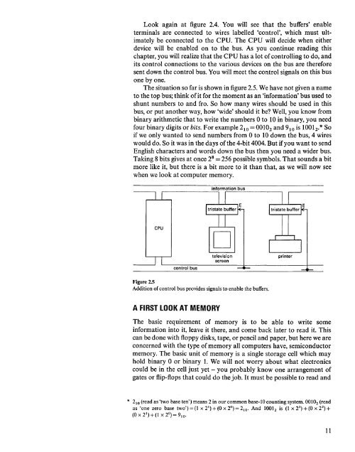
Look again at figure 2.4. You will see that the buffers' enable<br />
terminals are connected to wires labelled 'control', which must ultimately<br />
be connected to the CPU. The CPU will decide when either<br />
device will be enabled on to the bus. As you continue reading this<br />
chapter, you will realize that the CPU has a lot of controlling to do, <strong>and</strong><br />
its control connections to the various devices on the bus are therefore<br />
sent down the control bus. You will meet the control signals on this bus<br />
one by one.<br />
The situation so far is shown in figure 2.5. We have not given a name<br />
to the top bus; think of it for the moment as an 'information' bus used to<br />
shunt numbers to <strong>and</strong> fro. So how many wires should be used in this<br />
bus, or put another way, how 'wide' should it be? Well, you know from<br />
binary arithmetic that to write the numbers 0 to 10 in binary, you need<br />
four binary digits or bits. For example 2 10 = 0010 2 <strong>and</strong> 9 10 is 1001 2 .* So<br />
if we only wanted to send numbers from 0 to 10 down the bus, 4 wires<br />
would do. So it was in the days of the 4-bit 4004. But if you want to send<br />
English characters <strong>and</strong> words down the bus then you need a wider bus.<br />
Taking 8 bits gives at once 2 8 = 256 possible symbols. That sounds a bit<br />
more like it, but there is a bit more to it than that, as we will now see<br />
when we look at computer memory.<br />
,...--------,<br />
information<br />
bus<br />
CPU<br />
control<br />
bus<br />
D<br />
television<br />
screen<br />
printer<br />
Figure 2.5<br />
Addition of control bus provides signals to enable the buffers.<br />
A FIRST LOOK AT MEMORY<br />
The basic requirement of memory is to be able to write some<br />
information into it, leave it there, <strong>and</strong> come back later to read it. This<br />
can be done with floppy disks, tape, or pencil <strong>and</strong> paper, but here we are<br />
concerned with the type of memory all computers have, semiconductor<br />
memory. The basic unit of memory is a single storage cell which may<br />
hold binary 0 or binary 1. We will not worry about what electronics<br />
could be in the cell just yet - you probably know one arrangement of<br />
gates or flip-flops that could do the job. It must be possible to read <strong>and</strong><br />
* 2 10 (read as 'two base ten') means 2 in our common base-IO counting system. 0010 2 (read<br />
as 'one zero base two') = (l X 2 1 ) + (0 x 2°) = 2 10 • And 1001 2 is (1 X 2 3 ) + (0 X 2 2 ) +<br />
(Ox2 1 )+(l X 2°)=9 10 •<br />
11


