

Microcomputer Circuits and Processes
Microcomputer Circuits and Processes
Microcomputer Circuits and Processes

You also want an ePaper? Increase the reach of your titles
YUMPU automatically turns print PDFs into web optimized ePapers that Google loves.
says that this voltage, 0001, is smaller than 0011, Vin. So the comparator<br />
outputs a logical 1 which is latched into the SAR. The SAR holds 0011,<br />
bits 3, 2, <strong>and</strong> 1 being latched at 0, 0, <strong>and</strong> 1 respectively.<br />
4 Finally, the SAR makes bit 0 go low, outputting 0010, bits 1 to 3<br />
remaining latched. The D-to-A converts, <strong>and</strong> now the comparator sees<br />
two equal voltages <strong>and</strong> outputs a logical 0 which is latched into the<br />
SAR (note that the comparator is biased).<br />
comparator<br />
digital-to-analogue<br />
data<br />
bus<br />
\.,..----------, i<br />
SAR<br />
control<br />
enable<br />
Jl..Jl...n..<br />
start<br />
clock conversion<br />
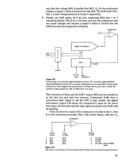
Figure 4.29<br />
Components of a successive approximation converter. The successive approximation<br />
register (SAR) drives the D-to-A converter, which passes on the equivalent voltage to the<br />
comparator. This compares the approximation voltage with JIIn> the input voltage. The<br />
outcome of this comparison tells the SAR what to do next.<br />
The conversion is done, <strong>and</strong> the SAR's output, 0010, can be enabled on<br />
to the data bus <strong>and</strong> read into memory. Commercial SARs have a<br />
'conversion done' signal to tell the CPU it may transfer the digital<br />
information. Figure 4.30 shows the comparator's input for the above<br />
four stages of conversion <strong>and</strong> the logic signal sent back to the SAR with<br />
its meaning.<br />
Note also that the output of the comparator is 0, then 0, then 1, then<br />
0, as the conversion proceeds. This is the correct binary value for Vi",<br />
comparator<br />
1 r> 1<br />
D-to-A input control<br />
output voltage to SAR<br />
1 0111 0010 0 too high<br />
2 0011 0010 0 too high<br />
3 0001 0010 1 too low<br />
4 0010 0010 0 just right - both voltages<br />
equal<br />
Figure 4.30<br />
The input to <strong>and</strong> output of the comparator for the four steps of successive approximation.<br />
63


