

Microcomputer Circuits and Processes
Microcomputer Circuits and Processes
Microcomputer Circuits and Processes

You also want an ePaper? Increase the reach of your titles
YUMPU automatically turns print PDFs into web optimized ePapers that Google loves.
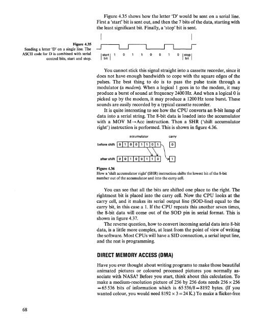
Figure 4.35 shows how the letter 'D' would be sent on a serial line.<br />
First a 'start' bit is sent out, <strong>and</strong> then the 7 bits of the data, starting with<br />
the least significant bit. Finally, a 'stop' bit is sent.<br />
I<br />
Figure 4.35 •.... ------. r----, II I<br />
Sending a letter 'D' on a single line. The -.J L-.J L....-_---I L...__ .....J<br />
ASCII code for D is combined with serial I start I 1 0 0 0 0 I stop I<br />
control bits, start <strong>and</strong> stop. bit bit<br />
You cannot stick this signal straight into a cassette recorder, since it<br />
does not have enough b<strong>and</strong>width to cope with the square edges of the<br />
pulses. The best thing to do is to pass the pulse train through a<br />
modulator (a modem). When a logical 1 goes in to the modem, it may<br />
produce a burst of sound at frequency 2400 Hz. And when a logical 0 is<br />
picked up by the modem, it may produce a 1200Hz tone burst. These<br />
sounds are easily recorded by a typical cassette recorder.<br />
It is quite interesting to see how the CPU converts an 8-bit lump of<br />
data into a serial string. The 8-bit data is loaded into the accumulator<br />
with a MOV M-+Acc instruction. Then a SHR ('shift accumulator<br />
right') instruction is performed. This is shown in figure 4.36.<br />
accumulator<br />
carry<br />
after shift<br />
L...-L...-L...-L...-L...-L...-.L--.L......J<br />
Figure 4.36<br />
How a 'shift accumulator right' (SHR) instruction shifts the lowest bit of the 8-bit<br />
number out of the accumulator <strong>and</strong> into the carry cell.<br />
You can see that all the bits are shifted one place to the right. The<br />
rightmost bit is placed into the carry cell. Now the CPU looks at the<br />
carry cell, <strong>and</strong> it makes its serial output line (SOD-line) equal to the<br />
carry bit, in this case a 1. If the CPU repeats this another seven times,<br />
the 8-bit data will come out of the SOD pin in serial format. This is<br />
shown in figure 4.37.<br />
The reverse question, how to convert incoming serial data into 8-bit<br />
data, is a little more complex, at least from the point of view of writing<br />
the software. Most CPUs will have a SID connection, a serial input line,<br />
<strong>and</strong> the rest is programming.<br />
DIRECT MEMORY ACCESS (DMA)<br />
Have you ever thought about writing programs to make those beautiful<br />
animated pictures or coloured processed pictures you normally associate<br />
with NASA? Before you start, think about this calculation. To<br />
make a medium-resolution picture of 256 by 256 dots needs 256 x 256<br />
= 65 536 bits of information which is 65536/8 =8192 bytes. (If you<br />
wanted colour, you would need 8192 x 3=24 K.) To make a flicker-free<br />
68


