

Microcomputer Circuits and Processes
Microcomputer Circuits and Processes
Microcomputer Circuits and Processes

Create successful ePaper yourself
Turn your PDF publications into a flip-book with our unique Google optimized e-Paper software.
this R is in series with the next horizontal R, <strong>and</strong> so on. For a ladder of<br />
any length, the input resistance is just R.<br />
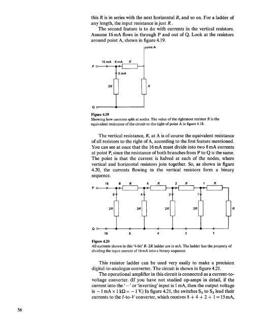
The second feature is to do with currents in the vertical resistors.<br />
Assume 16mA flows in through P <strong>and</strong> out of Q. Look at the resistors<br />
around point A, shown in figure 4.19.<br />
point A<br />
16mA 8 mA R<br />
2R<br />
R<br />
Qo---<br />
......• --------'<br />
Figure 4.19<br />
Showing how currents split at nodes. The value of the rightmost resistor R is the<br />
equivalent resistance ofthe circuit to the right of point A in figure 4.18.<br />
The vertical resistance, R, at A is of course the equivalent resistance<br />
of all resistors to the right of A, according to the first feature mentioned.<br />
You can see at once that the 16 rnA must divide into two 8 rnA currents<br />
at point P, since the resistance of both branches from P to Q is the same.<br />
The point is that the current is halved at each of the nodes, where<br />
vertical <strong>and</strong> horizontal resistors join together. So, as shown in figure<br />
4.20, the currents flowing in the vertical resistors form a binary<br />
sequence.<br />
16<br />
2R<br />
R<br />
Qo---E:---4"'---~--"----E---<br />
16 8 4 2<br />
--*""--'--~--""'"<br />
Figure 4.20<br />
All currents shown in this '4-bit' R-2R ladder are in rnA. The ladder has the property of<br />
dividing the input current of 16mA into a binary sequence.<br />
This resistor ladder can be used very easily to make a precision<br />
digital-to-analogue converter. The circuit is shown in figure 4.21.<br />
The operational amplifier in this circuit is connected as a current-tovoltage<br />
converter. (If you have not studied op-amps in detail, if the<br />
current into the' -' or 'inverting' input is 1 rnA, then the output voltage<br />
is -1 rnA x 1 kQ = -1 V.) In figure 4.21, the switches So to S3 lead their<br />
currents to the I -to- V converter, which receives 8 + 4 + 2 + 1= 15 rnA,<br />
56


