

Microcomputer Circuits and Processes
Microcomputer Circuits and Processes
Microcomputer Circuits and Processes

Create successful ePaper yourself
Turn your PDF publications into a flip-book with our unique Google optimized e-Paper software.
have addresses from 001000000000 (512 10 ) to 0010 11111111 (767 10 ),<br />
<strong>and</strong> the third from 010000000000 (1024 10 ) to 0100 11111111 (1279 10 ),<br />
There is a nasty gap between 767 <strong>and</strong> 1024.Secondly, this arrangement<br />
is wasteful of power. There are 2 8 = 256 possible combinations of 8 bits,<br />
<strong>and</strong> if these were decoded properly, they could control 256 pages of<br />
memory, i.e. 256 x 256 bytes, the magic 65536 (64K) bytes.<br />
16-bit<br />
address<br />
bus<br />
8 bits<br />
I<br />
8 bits<br />
0<br />
, E<br />
4-bit<br />
C<br />
16 outputs<br />
1<br />
0 - only one goes high<br />
input 2 0 at any time<br />
3 E<br />
R<br />
15<br />
,<br />
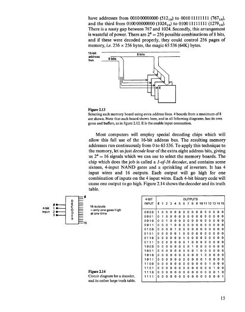
Figure 2.13<br />
Selecting each memory board using extra address lines. 4 boards from a maximum of 8<br />
are shown. Note that each board shown here, <strong>and</strong> in all following diagrams, has its own<br />
gates <strong>and</strong> buffers, as in figure 2.12. E is the enable input connection.<br />
Most computers will employ special decoding chips which will<br />
allow this full use of the 16-bit address bus. The resulting memory<br />
addresses run continuously from 0 to 65536. To apply this technique to<br />
the memory, let us just decode four of the extra eight address bits, giving<br />
us 2 4 = 16 signals which we can use to select the memory boards. The<br />
chip which does the job is called a 1-of16 decoder, <strong>and</strong> contains some<br />
sixteen, 4-input NAND gates <strong>and</strong> a sprinkling of inverters. It has 4<br />
input wires <strong>and</strong> 16 outputs. Each output will go high for one<br />
combination of inputs on the 4 input wires. Each 4-bit binary code will<br />
cause one output to go high. Figure 2.14 shows the decoder <strong>and</strong> its truth<br />
table.<br />
Figure 2.14<br />
Circuit diagram for a decoder,<br />
<strong>and</strong> its rather large truth table.<br />
4-BIT<br />
OUTPUTS<br />
INPUT 2 345 6 7 8 9101112131415<br />
" 1<br />
0000 1 0 0 0 0 0 0 0 0 0 0 0 0 0 0 0<br />
0001 0 1 0 0 0 0 0 0 0 0 0 0 0 0 0 0<br />
0010 0 0 1 0 0 0 0 0 0 0 0 0 0 0 0 0<br />
001 1 0 0 0 1 0 0 0 0 0 0 0 0 0 0 0 0<br />
0100 0 0 0 0 1 0 0 0 0 0 0 0 0 0 0 0<br />
0101 0 0 0 0 0 1 0 0 0 0 0 0 0 0 0 0<br />
0110 0 0 0 0 0 0 1 0 0 0 0 0 0 0 0 0<br />
01 1 1 0 0 0 0 0 0 0 1 0 0 0 0 0 0 0 0<br />
1000 0 0 0 0 0 0 0 0 1 0 0 0 0 0 0 0<br />
1001 0 0 0 0 0 0 0 0 0 1 0 0 0 0 0 0<br />
1010 0 0 0 0 0 0 0 0 0 0 1 0 0 0 0 0<br />
1011 0 0 0 0 0 0 0 0 0 0 0 1 0 0 0 0<br />
1100 0 0 0 0 0 0 0 0 0 0 0 0 1 0 0 0<br />
1 1 01 0 0 0 0 0 0 0 0 0 0 0 0 0 1 0 0<br />
1 1 1 0 0 0 0 0 0 0 0 0 0 0 0 0 0 0 1 0<br />
1 1 1 1 0 0 0 0 0 0 0 0 0 0 0 0 0 0 0 1<br />
15


