

Microcomputer Circuits and Processes
Microcomputer Circuits and Processes
Microcomputer Circuits and Processes

You also want an ePaper? Increase the reach of your titles
YUMPU automatically turns print PDFs into web optimized ePapers that Google loves.
That is the principle of the converter. The commercial DAC 08 chip<br />
from Precision Monolithics incorporates transistors as switches. Currents<br />
can be switched faster than voltages (the DAC 08 takes only 85 ns<br />
to respond to a change in binary number), which is another reason why<br />
the R-2R ladder technique is popular.<br />
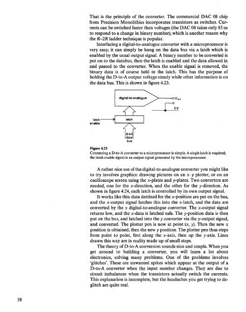
Interfacing a digital-to-analogue converter with a microprocessor is<br />
very easy; it can simply be hung on the data bus via a latch which is<br />
enabled by the usual output signal. A binary number to be converted is<br />
put on to the databus, then the latch is enabled <strong>and</strong> the data allowed in<br />
<strong>and</strong> passed to the converter. When the enable signal is removed, the<br />
binary data is of course held in the latch. This has the purpose of<br />
holding the D-to-A output volt~ge steady while other information is on<br />
the data bus. This is shown in figure 4.23.<br />
digital-to-analogue<br />
~---oVout<br />
latch--~<br />
enable 1--_---,.,,__ .....•<br />
Figure 4.23<br />
Connecting a D-to-A converter to a microprocessor is simple. A single latch is required;<br />
the latch enable signal is an output signal generated by the microprocessor.<br />
A rather nice use ofthe digital-to-analogue converter you might like<br />
to try involves graphics: draw~ng pictures on an x-y plotter, or on an<br />
oscilloscope screen using the x-plates <strong>and</strong> y-plates. Two converters are<br />
needed, one for the x-direction, <strong>and</strong> the other for the y-direction. As<br />
shown in figure 4.24, each latch is controlled by its own output signal.<br />
It works like this: data destined for the x-position are put on the bus,<br />
<strong>and</strong> the x-output signal latches this into the x-latch, <strong>and</strong> the data are<br />
converted by the x digital-to-analogue converter. The x-output signal<br />
returns low, <strong>and</strong> the x-data is latched safe. The y-position data is then<br />
put on the bus, <strong>and</strong> latched into the y converter via the y-output signal,<br />
<strong>and</strong> converted. The plotter pen is now at point (x, y). Then the new x<br />
position is obtained, then the new y position. The plotter pen thus steps<br />
from point to point, first along the x-axis, then up the y-axis. Lines<br />
drawn this way are in reality made up of small steps.<br />
The theory of D-to-A conversion sounds nice <strong>and</strong> simple. When you<br />
get around to building a converter, you will learn a lot about<br />
electronics, solving many problems. One of the problems involves<br />
'glitches'. These are unwanted spikes which appear at the output of a<br />
D-to-A converter when the input number changes. They are due to<br />
circuit imbalances when the transistors actually switch the currents.<br />
This explanation is incomplete, but the headaches you get trying to deglitch<br />
are quite real.<br />
58


