

Microcomputer Circuits and Processes
Microcomputer Circuits and Processes
Microcomputer Circuits and Processes

Create successful ePaper yourself
Turn your PDF publications into a flip-book with our unique Google optimized e-Paper software.
That is the end of the program, except for the STOP cycles. This<br />
instruction, which has code 0000 lives at memory address 0110. A<br />
glance at the program counter in figure 3.25 should convince you that<br />
the program counter holds this address.<br />
As described in Chapter 2, computer engineers work extensively with<br />
timing diagrams, showing data transfers <strong>and</strong> control signal changes all<br />
on one diagram. To draw a complete timing diagram for the program<br />
we have just run through would take a very long piece of paper, but<br />
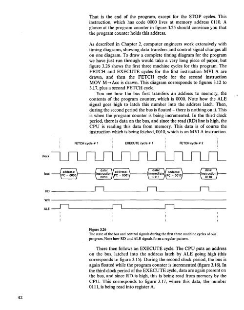
figure 3.26 shows the first three machine cycles for this program. The<br />
FETCH <strong>and</strong> EXECUTE cycles for the first instruction MVI A are<br />
drawn, <strong>and</strong> then the FETCH cycle for the second instruction<br />
MOV M~Acc is drawn. This diagram corresponds to figures 3.12 to<br />
3.17, plus a second FETCH cycle.<br />
You see how the bus first transfers an address to memory, the<br />
contents. of the program counter, which is 0000. Note how the ALE<br />
signal goes high to latch this number into the address latch. Then,<br />
during the second period the bus is floated - there is nothing on it. This<br />
is when the program counter is being incremented. In the third clock<br />
period, there is data on the bus, <strong>and</strong> since the read (RD) line is high, the<br />
CPU is reading this data from memory. This data is of course the<br />
instruction which is being fetched, 0010, which is an MVI A instruction.<br />
FETCH cycle # 1 EXECUTE cycle # 1 FETCH cycle # 2<br />
clock<br />
bus<br />
RD --IIlL.. ----JIlL- IlL- _<br />
WR ----------------------------------<br />
ALE -rlL..- --


