

Microcomputer Circuits and Processes
Microcomputer Circuits and Processes
Microcomputer Circuits and Processes

You also want an ePaper? Increase the reach of your titles
YUMPU automatically turns print PDFs into web optimized ePapers that Google loves.
These equally spaced voltages are fed to a line of comparators. The<br />
second input to each comparator is connected to a common point, <strong>and</strong><br />
~O' the signal to be converted, is fed in here. Now, if ~n is zero, all the<br />
comparators give output logic low, as may be seen from the comparator<br />
characteristics shown in figure 4.26. If ~n increases to, say, 2.7 V, then<br />
comparator 0 will go high, the others remaining low. And if ~n lies<br />
between 4 <strong>and</strong> 6 V then both comparators 0 <strong>and</strong> 1will go high. So as the<br />
input voltage rises, each comparator will, in turn, go logical high.<br />
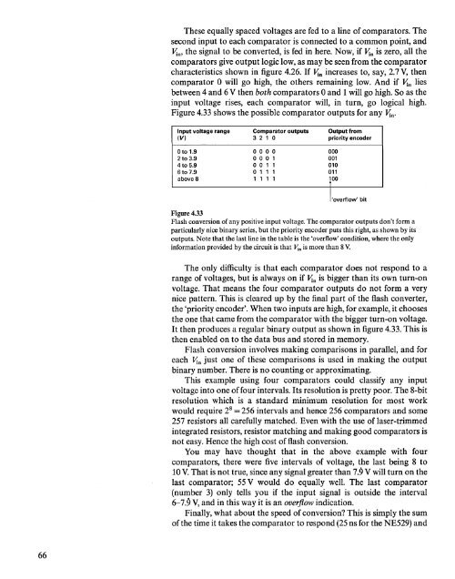
Figure 4.33 shows the possible comparator outputs for any ~n.<br />
Input voltage range<br />
(V)<br />
Comparator<br />
321 0<br />
outputs<br />
Output from<br />
priority encoder<br />
o to 1.9<br />
2 to 3.9<br />
4to 5.9<br />
6to 7.9<br />
above 8<br />
o 0 0 0<br />
000 1<br />
001 1<br />
o 1 1 1<br />
1 1 1 1<br />
000<br />
001<br />
010<br />
011<br />
lOO<br />
I'overflow'<br />
bit<br />
Figure 4.33<br />
Flash conversion of any positive input voltage. The comparator outputs don't form a<br />
particularly nice binary series, but the priority encoder puts this right, as shown by its<br />
outputs. Note that the last line in the table is the 'overflow' condition, where the only<br />
information provided by the circuit is that Vln is more than 8 V.<br />
The only difficulty is that each comparator does not respond to a<br />
range of voltages, but is always on if ~n is bigger than its own turn-on<br />
voltage. That means the four comparator outputs do not form a very<br />
nice pattern. This is cleared up by the final part of the flash converter,<br />
the 'priority encoder'. When two inputs are high, for example, it chooses<br />
the one that came from the comparator with the bigger turn-on voltage.<br />
It then produces a regular binary output as shown in figure 4.33. This is<br />
then enabled on to the data bus <strong>and</strong> stored in memory.<br />
Flash conversion involves making comparisons in parallel, <strong>and</strong> for<br />
each ~n just one of these comparisons is used in making the output<br />
binary number. There is no counting or approximating.<br />
This example using four comparators could classify any input<br />
voltage into one of four intervals. Its resolution is pretty poor. The 8-bit<br />
resolution which is a st<strong>and</strong>ard minimum resolution for most work<br />
would require 2 8 = 256 intervals <strong>and</strong> hence 256 comparators <strong>and</strong> some<br />
257 resistors all carefully matched. Even with the use of laser-trimmed<br />
integrated resistors, resistor matching <strong>and</strong> making good comparators is<br />
not easy. Hence the high cost of flash conversion.<br />
You may have thought that in the above example with four<br />
comparators, there were five intervals of voltage, the last being 8 to<br />
10 V. That is not true, since any signal greater than 7.9 V will turn on the<br />
last comparator; 55 V would do equally well. The last comparator<br />
(number 3) only tells you if the input signal is outside the interval<br />
6-7.9 V, <strong>and</strong> in this way it is an overflow indication.<br />
Finally, what about the speed of conversion? This is simply the sum<br />
of the time it takes the comparator to respond (25 ns for the NE529) <strong>and</strong><br />
66


