

Microcomputer Circuits and Processes
Microcomputer Circuits and Processes
Microcomputer Circuits and Processes

Create successful ePaper yourself
Turn your PDF publications into a flip-book with our unique Google optimized e-Paper software.
Now this signal goes high only when the CPU executes an OUTput<br />
instruction to this device, <strong>and</strong> only then will the data be allowed<br />
through the buffer. This signal is also connected to the display driver<br />
'latch' terminal. When the signal is high, the data is allowed into the<br />
display, but when it goes low, after the OUTput instruction is finished,<br />
the data is latched into the display <strong>and</strong> the number will be displayed. If<br />
this were not done, then you would never see any numbers, since the<br />
output instruction takes, say, a millisecond to be executed. The latch<br />
holds the data firm until the next output instruction is performed, when<br />
the displayed number must be updated.<br />
Extending this to 4, 8, or 10 digits is easy. You could use a displaydriver<br />
chip plus output buffer for each digit, which would then appear<br />
to the CPU as separate output ports. Outputting a number to port 1<br />
would set up that number in the first digit, outputting to the second<br />
port would set up the second digit, <strong>and</strong> so on. It would work, but uses a<br />
lot of chips. There is a simpler way. To underst<strong>and</strong> how this works, we<br />
must take a look inside the display (figure 4.12).<br />
anode<br />
connections<br />
common<br />
cathode<br />
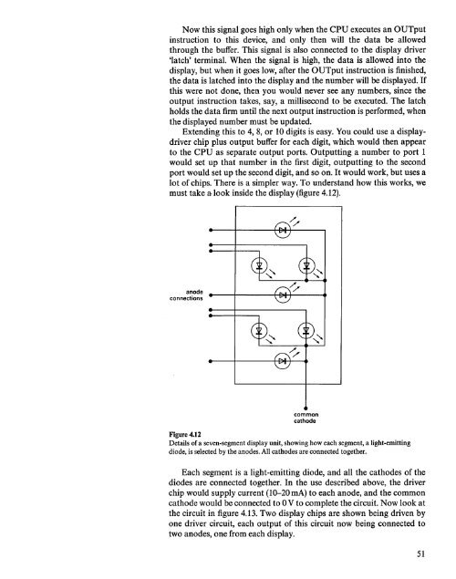
Figure 4.12<br />
Details of a seven-segment display unit, showing how each segment, a light-emitting<br />
diode, is selected by the anodes. All cathodes are connected together.<br />
Each segm~nt is a light-emitting diode, <strong>and</strong> all the cathodes of the<br />
diodes are connected together. In the use described above, the driver<br />
chip would supply current (10-20 rnA) to each anode, <strong>and</strong> the common<br />
cathode would be connected to 0 V to complete the circuit. Now look at<br />
the circuit in figure 4.13. Two display chips are shown being driven by<br />
one driver circuit, each output of this circuit now being connected to<br />
two anodes, one from each display.<br />
51


