

Microcomputer Circuits and Processes
Microcomputer Circuits and Processes
Microcomputer Circuits and Processes

Create successful ePaper yourself
Turn your PDF publications into a flip-book with our unique Google optimized e-Paper software.
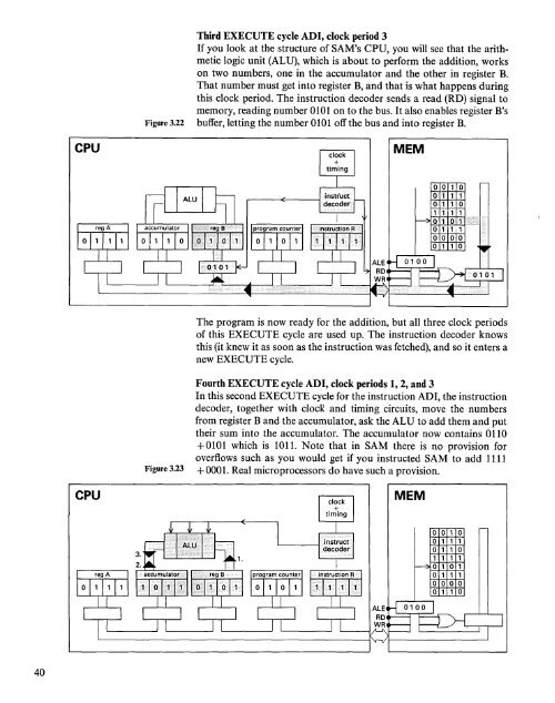
Third EXECUTE cycle ADI, clock period 3<br />
If you look at the structure of SAM's CPU, you will see that the arithmetic<br />
logic unit (ALU), which is about to perform the addition, works<br />
on two numbers, one in the accumulator <strong>and</strong> the other in register B.<br />
That number must get into register B, <strong>and</strong> that is what happens during<br />
this clock period. The instruction decoder sends a read (RD) signal to<br />
memory, reading number 0101 on to the bus. It also enables register B's<br />
Figure 3.22 buffer, letting the number 0101 off the bus <strong>and</strong> into register B.<br />
CPU<br />
MEM<br />
a<br />
a<br />
The program is now ready for the addition, but all three clock periods<br />
of this EXECUTE cycle are used up. The instruction decoder knows<br />
this (it knew it as soon as the instruction was fetched), <strong>and</strong> so it enters a<br />
new EXECUTE cycle.<br />
Fourth EXECUTE cycle ADI, clock periods 1, 2, <strong>and</strong> 3<br />
In this second EXECUTE cycle for the instruction ADI, the instruction<br />
decoder, together with clocK <strong>and</strong> timing circuits, move the numbers<br />
from register B <strong>and</strong> the accumulator, ask the ALU to add them <strong>and</strong> put<br />
their sum into the accumulator. The accumulator now contains 0110<br />
+0101 which is 1011. Note that in SAM there is no provision for<br />
overflows such as you would get if you instructed SAM to add 1111<br />
Figure 3.23 +0001. Real microprocessors do have such a provision.<br />
CPU<br />
MEM<br />
40


