

Microcomputer Circuits and Processes
Microcomputer Circuits and Processes
Microcomputer Circuits and Processes

Create successful ePaper yourself
Turn your PDF publications into a flip-book with our unique Google optimized e-Paper software.
A typical bubble unit contains 300 loops, each with 4096 cells,<br />
around which bubbles circulate. Two tracks communicate with the<br />
loops: the input track which carries bubbles from a generator - a loop<br />
of conductor carrying the input current pulse which locally reverses the<br />
bias field <strong>and</strong> creates a bubble - <strong>and</strong> the output track. The latter leads<br />
to a bubble detector, a magnetoresistive. device. When a magnetic<br />
bubble passes by this device the change in magnetic field strength<br />
causes the resistance of the device to change, which in turn changes a<br />
current passing through the device. To complete the memory, a bit of<br />
control is needed to synchronize bubble production <strong>and</strong> loading, or<br />
unloading <strong>and</strong> detecting. Then, with the magnetic field rotating at<br />
50kHz, data may be got from the memory in about 0.1ms. So bubble<br />
memory is not particularly slow, it can store vast amounts of data, <strong>and</strong>,<br />
unlike disk storage, has no moving mechanical parts to fail. It is nonvolatile<br />
<strong>and</strong> so saves its contents when the computer is switched off or if<br />
power fails.<br />
APPLICATION NOTE - SEVEN-SEGMENT DISPLAY<br />
How does a calculator-type display work? There may be up to ten~digits<br />
used to display a large number. How can such a display be hooked up<br />
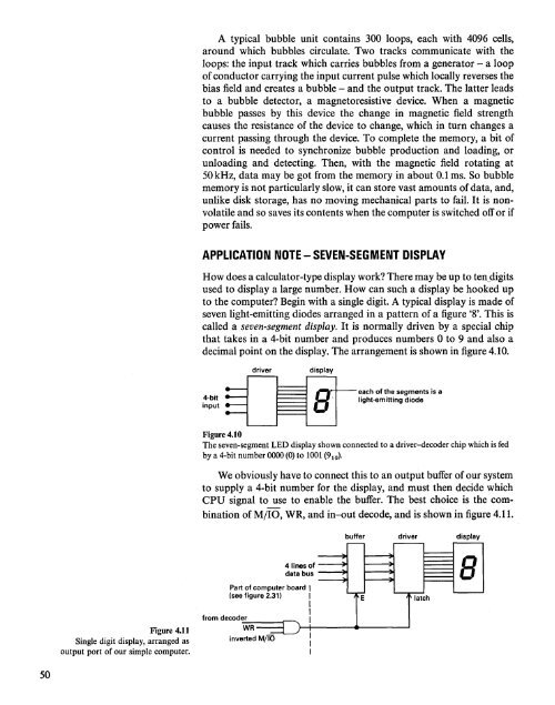
to the computer? Begin with a single digit. A typical display is made of<br />
seven light-emitting diodes arranged in a pattern of a figure '8'. This is<br />
called a seven-segment display. It is normally driven by a special chip<br />
that takes in a 4-bit number <strong>and</strong> produces numbers 0 to 9 <strong>and</strong> also a<br />
decimal point on the display. The arrangement is shown in figure 4.10.<br />
4-bit<br />
input<br />
driver<br />
display<br />
8<br />
each of the segments<br />
light-emitting diode<br />
is a<br />
Figure 4.10<br />
The seven-segment LED display shown connected to a driver-decoder chip which is fed<br />
by a 4-bit number 0000 (0) to 1001 (9 10 ).<br />
We obviously have to connect this to an output buffer of our system<br />
to supply a 4-bit number for the display, <strong>and</strong> must then decide which<br />
CPU signal to use to enable the buffer. The best choice is the combination<br />
ofM/IO, WR, <strong>and</strong> in-out decode, <strong>and</strong> is shown in figure 4.11.<br />
buffer driver display<br />
4 lines of<br />
data bus<br />
~8<br />
Figure 4.11<br />
Single digit display, arranged as<br />
output port of our simple computer.<br />
Part of computer board I<br />
(see figure 2.31) I<br />
I<br />
from decoder I<br />
inverted<br />
WR 1--+-----4....----.....1<br />
M/IO<br />
E<br />
latch<br />
50


