

Microcomputer Circuits and Processes
Microcomputer Circuits and Processes
Microcomputer Circuits and Processes

Create successful ePaper yourself
Turn your PDF publications into a flip-book with our unique Google optimized e-Paper software.
digital-to-analogue<br />
x-output --~<br />
v-output --~<br />
x-v plotter or<br />
oscilloscope<br />
digital-to-analogue<br />
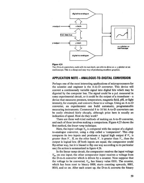
Figure 4.24<br />
Two D-to-A converters, each with its own latch, are able to drive an x-y plotter or an<br />
oscilloscope. This is a cheap <strong>and</strong> easy way of producing excellent graphics.<br />
APPLICATION NOTE - ANALOGUE-TO-DIGITAL CONVERSION<br />
Perhaps one of the most interesting applications of microprocessors for<br />
the scientist <strong>and</strong> engineer is the A-to-D converter. This device will<br />
convert a continuously variable signal into digital bits which may be<br />
digested by the computer bus. The signal could be a p.d. measured in<br />
some experimental circuit, or it could be the output of a transducer - a<br />
device that measures pressure, temperature, magnetic field, pH, or light<br />
intensity, for example, <strong>and</strong> converts these to a voltage. Using an A-to-D<br />
converter, an experimenter can build automatic, programmable<br />
measuring instruments. Commercial 8 to 16 bit A-to-D converters can<br />
be easily obtained fairly cheaply, although price here is usually an<br />
indication of speed. How do they work?<br />
There are three well-tried methods of making an A-to-D converter,<br />
<strong>and</strong> each of these involves making a comparison. Figure 4.25 shows the<br />
first method, the linear ramp technique.<br />
Here, the input voltage Vin is compared with the output of a digitalto-analogue<br />
converter, using a chip called a 'comparator'. This chip<br />
compares its two inputs <strong>and</strong> produces a logical high output if V+ is<br />
greater than V_. If, on the other h<strong>and</strong>, V_ is greater than V+, then the<br />
output is logical low. (If both inputs are equal, the comparator could<br />
flip either way, but it is biased to flip one way according to its particular<br />
use.) Its action is summarized in figure 4.26.<br />
In the linear ramp circuit, the comparator receives the input voltage<br />
Vin' on one input; the other comparator input receives a voltage from<br />
the D-to-A converter which is driven by a counter. Now suppose that<br />
the voltage to be converted, Vin' has binary value 0101. The counter,<br />
which has been reset to binary 0000, starts counting upwards, 0001,<br />
0010, <strong>and</strong> so on. After each count up, the D-to-A converts the binary<br />
59


