

Microcomputer Circuits and Processes
Microcomputer Circuits and Processes
Microcomputer Circuits and Processes

Create successful ePaper yourself
Turn your PDF publications into a flip-book with our unique Google optimized e-Paper software.
Where exactly is this common line connected to the processor? An<br />
obvious place would be one of the input lines. The program would<br />
instruct the processor to look at this line from time to time. If it is low,<br />
then no key is pressed. If it is high, then some key has been pressed. The<br />
key number is the last number the processor has outputted.<br />
Most processors have a special sort of input called an<br />
INTERRUPT, which could have been used to hook up to the common<br />
line. When the interrupt goes high, the program jumps to another<br />
subprogram which 'services' the interrupt. Here the servicing would<br />
involve getting the last number outputted from the register.<br />
APPLICATION NOTE - DIGITAL-TO-ANALOGUE CONVERSION<br />
You may wish to set up the computer so that it can control smoothly<br />
the speed of a motor, the brightness of a light, or the position of a<br />
drawing pen. In all of these applications, a smoothly varying voltage,<br />
say between 0 <strong>and</strong> 10, is needed from a computer that has been designed<br />
to work on logic levels 0 <strong>and</strong> 1 of 0 V <strong>and</strong> 5 V respectively. Some sort of<br />
conversion is needed. Consider a digital-to-analogue converter which<br />
takes in a 4-bit digital number <strong>and</strong> gives an output voltage between 0<br />
<strong>and</strong> 15. You will need to know how an operational amplifier works,<br />
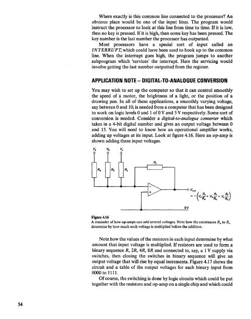
adding up voltages at its input. Look at figure 4.16. Here an op-amp is<br />
shown adding three input voltages.<br />
Figure 4.16<br />
A reminder of how op-amps can add several voltages. Note how the resistances R a to R c<br />
determine by how much each voltage is multiplied before the addition.<br />
ov<br />
Note how the values of the resistors in each input determine by what<br />
amount that input voltage is multiplied. If resistors are used to form a<br />
binary sequence R, 2R, 4R, 8R <strong>and</strong> connected to, say, a 1V supply via<br />
switches, then closing the switches in binary sequence will give an<br />
output voltage that will rise by equal increments. Figure 4.17 shows the<br />
circuit <strong>and</strong> a table of the output voltages for each binary ipput from<br />
0000 to 1111.<br />
Of course, the switching-is done by logic circuits which could be put<br />
together with the resistors <strong>and</strong> op-amp on a single chip <strong>and</strong> which could<br />
54


